Introduction
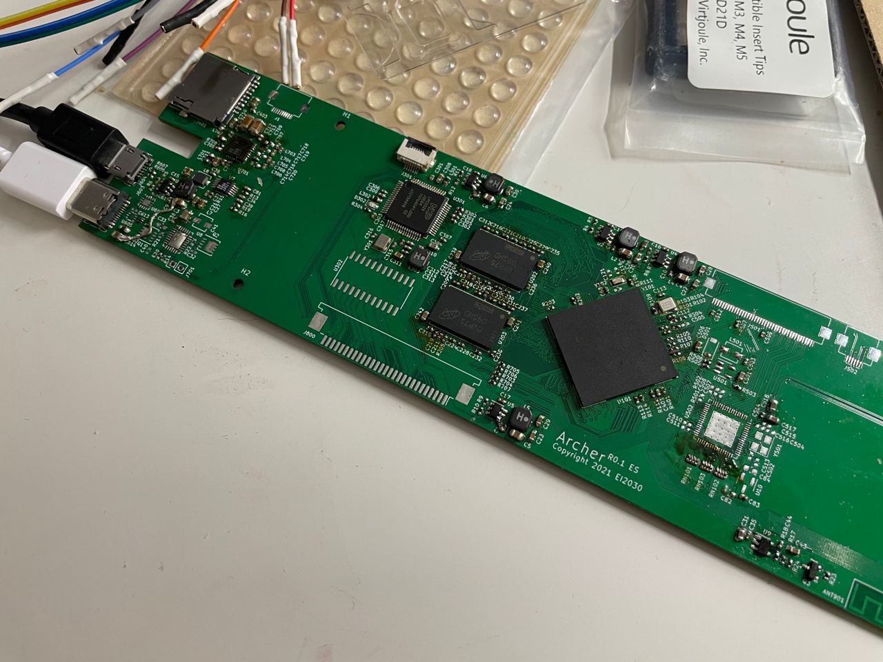
This blog post is about the initial board bring up process of the Archer. Archer is the codename for our EPD laptop prototype at EI2030. This is not a comprehensive bringup guide, but rather document the issues I found and the corresponding solutions. The processor being used is the i.MX 7Dual.
DDR
DDR Stress Test
When there is no vaild boot devices, i.MX would enter mfgtools or USB recovery mode. In this mode the DDR stress test tool provided by NXP could be used to test the DDR read/ write leveling values. Though generally if the board is well designed, it should pass the stress test at room temperature without special calibration.
One thing to note is that, in Freescale SoCs, DDR3-800 is actually DDR3-792, and DDR3-1066 is actually DDR3-1056. Enter 396 MHz and 528 MHz respectively to test two modes.
DDR frequency
On i.MX7D, the DDR frequency could be set from anywhere up to 528MHz (DDR3-1056). By default, Boot ROM sets the DDR PLL to 1056MHz. Neither u-boot nor kernel would touch the DDR PLL settings. In kernel, the kernel would switch the DDR frequency between 24MHz, 99MHz, and 528MHz by choosing the clock source from CLKOSC, PFD396/4, and DDR PLL respectively. As an conclusion, to adjust the DDR clock frequency (for example, downclock from 1056 to 792), one could simply modify the DDR PLL settings in the DCD before u-boot starts.
Example:
/* Set DDR PLL to 792 MHz */
DATA 4 0x30360070 0x00113021
DATA 4 0x30360074 0x00113021
DATA 4 0x30360078 0x00113021
DATA 4 0x3036007C 0x00113021

DATA 4 0x30360070 0x00603021
DATA 4 0x30360074 0x00603021
DATA 4 0x30360078 0x00603021
DATA 4 0x3036007C 0x00603021

CHECK_BITS_SET 4 0x30360070 0x80000000
CHECK_BITS_SET 4 0x30360074 0x80000000
CHECK_BITS_SET 4 0x30360078 0x80000000
CHECK_BITS_SET 4 0x3036007C 0x80000000
U-Boot
U-Boot USB Boot
uuu could be used to load and start u-boot directly over USB. See the following example script:
uuu_version 1.2.135

SDP: boot -f u-boot-dtb.imx -nojump
SDP: write -f ../linux-imx/arch/arm/boot/zImage -addr 0x80800000
SDP: write -f ../linux-imx/arch/arm/boot/dts/imx7d-archer.dtb -addr 0x83000000
SDP: write -f ../buildroot-2021.02.2/output/images/rootfs.cpio.uboot -addr 0x86800000
SDP: jump -f u-boot-dtb.imx -ivt
SDP: done
If loading Linux/ buildroot is not necessary, the corresponding lines could be removed.
U-Boot SD Card Boot
To flash U-boot to SD card for SD boot:
#!/bin/sh
sudo dd if=u-boot-dtb.imx of=/dev/sdb bs=1k seek=1 conv=fsync
sync
On our board, the U-Boot initially failed to boot from the SD card. There could be multiple reasons why this is happening, but a common one being the board fails to read the SD card in SDR104 mode, due to non-working 1.8V/3.3V voltage switch, unmatched trace length, bad SI, etc. Limit the mode to HS usually solves the issue. One our board it was a bit more complicated (weird):
In u-boot, the card is detected, and works under 50MHz. Commands such as fatls and ext4ls works fine. But mmc info shows only 1-bit mode. In Linux, the kernel could detect the card but fails to read even just the partition table. It turned out the PCB fab screwed up and shorted D0 and D2:
https://twitter.com/zephray_wenting/status/1400235144301232131
Kernel
No output after jumping to kernel
Try enable the early console and see if it prints out anything with it:
earlycon=ec_imx6q,0x30860000,115200
The name ec_imx6q might be a bit misleading, but this is the correct driver to use for i.MX6/7/8. Please refer to the processors' RM or dtsi file for the UART base address.
If there is still no output using earlycon... I don't know. Probably check DDR?
Kernel hangs after "psci: probing for conduit method from DT"
The kernel would jump to the psci firmware after this line. Early versions of u-boot doesn't seems to be able to setup psci correctly when booting from mfgtools. Boot from SD or upgrade to latest version (imx v2020.04 5.4.70 2.3.0 works fine).
EPD
Waveform
The waveform is basically a look up table for the EPDC to determine how to drive the pixels.
The waveform file is independent to the resolution. So for example the device has a 1024x758 screen, and one could drive the screen with a waveform designed for a 800x600 screen. It should at least display some image. Maybe the greyscale wouldn't be correct with incorrect waveform file but it should display some recognizable image.
The waveform distributed by Eink is usually in .wbf format, while the i.MX SoC uses a converted binary format. There are 3 generations of EPDC:
- EPDC 1.0 (EPDC) in i.MX50
- EPDC 2.0 (EPDCv1/ EPDC) in i.MX6DL/SL
- EPDC 3.0 (EPDCv2) in i.MX6SLL/ULL and i.MX7D
(What a good naming scheme)
Note: NXP's documentation suggests that the EPDC in i.MX6ULL is not as powerful as the one in i.MX6SLL/ i.MX7D, but it still uses the EPDCv2 driver.
I am not entirely sure about the difference in the waveform formats across EPDC generations, but doesn't seem to be fully compatible. NXP has tool to convert from .wbf to .fw, which (I assume) could be obtained after signing an NDA with NXP. I am not sure about the EPDC used in the upcoming i.MX8ULP.
There are 2 versions of the waveform, one being 4bpp and another being 5bpp. Note 5bpp waveform doesn't mean it supports 32 level of greyscale, it only means it uses 5bpp internally to represent pixel states. Usually 5bpp waveforms only supports 4bpp greyscale.
5bpp greyscale is natively supported on i.MX7D EPDCv2 drivers, but not in eariler i.MX6 EDPC drivers. Technically this could be done: https://github.com/reMarkable/linux/commit/1817e72e30bfb426dcd7f9139610e6e98f3f7d77#diff-9ae293778274bb0c250df114b514f6f703586a613f1309b380fdf640c7651d99. Note it seems like all new waveforms released by Eink is 5bpp.
Timing
The timings are defined in mxc_epdc_v2_fb.c. It includes the resolution information. Usually the timing could be found from the screen specification, but it might not match the waveform. There are 3 important parameters in the timing: resolution, refresh rate, and duty cycle. The other parameters could be chose freely (within certain ranges) without affecting the image quality.
NOTE: In the mxc_epdc_v2_fb.c, the pixel clock is the DDR clock, in SDR mode it needs to be doubled. For example, setting it to 66MHz actually generates a 33MHz pixel clock. The applies to data rate only, the timing is still calculated at double frequency.
For example, the example configuration for ED060XH2C1:
- CLK: 40 MHz
- XRES: 1024
- YRES: 758
- Left Margin (Line Begin, LB): 12
- Right Margin (Line End, LE): 76
- Upper Margin (Frame Begin, FB): 4
- Lower Margin (Frame End, FE): 5
- Hsync Width (Line Sync, LS): 12
- Vsync Width (Frame Sync, FS), 2
- GDCLK_HP: 524
It is a 8 bit screen, so it transfer 4 pixels per clock, but because the clock is doubled, it only transfers 2 pixels. The total line time is 1024/2 + 12 + 76 + 12 = 612 clocks, and the frame rate is 40000000 / (612 * (758 + 4 + 5 + 2)) = 84.99 Hz. So it would work with a 85 Hz waveform. The GDCLK_HP controls the duty cycle, 524 / 612 ~= 85% duty cycle.
Our ED103TC2 uses a 130Hz waveform, so the timing should be configured to generate ~130Hz framerate. First choose an appropriate clock frequency, the clock frequency offered by EPDC driver is in fairly large steps:
32MHz\ 40MHz\ 60MHz\ 80MHz\ 96MHz\ 132MHz\ 160MHz
The ED103TC2 specifies a maximum clock frequency of 83.33MHz, so the maximum value could be used at EPDC side is 166MHz.
In this example, start with 96MHz. Because the screen is 16bit, it could transfer 4 pixels per DDR clock. With resolution of 1872*1404, by playing with the numbers, I got the following configuration: LB=8, LE=42, LS=12, FB=4, FE=5, FS=1, FR=128 Hz. Good enough. The line time is now 530 clocks, multply by 85%, we could get a GDCLK_HP of 450. Entering these numbers into the driver and verify it works fine.
Setting the timing to invalid values (such as zero sync width, over one period sync location etc.) could cause screen to not refresh at all (Mode0 init failed), or timeout during refresh.
Setting the timing to inappropriate values (too high or too low refresh rate, too short blanking, etc.) could cause screen to not display greyscales properly, having strange bars on screen, showing image with offset, etc. But generally it should display recognizable image in these cases.
Output Mode
The EPDCv2 driver always configure the screen to be scaned from top to bottom and uses 8bit data bus. This could be changed by modifying the driver:
    reg_val =
        ((epdc_mode->vscan_holdoff << EPDC_TCE_CTRL_VSCAN_HOLDOFF_OFFSET) &
         EPDC_TCE_CTRL_VSCAN_HOLDOFF_MASK)
        | EPDC_TCE_CTRL_SCAN_DIR_0_UP
        | EPDC_TCE_CTRL_SDDO_WIDTH_16BIT
        | EPDC_TCE_CTRL_PIXELS_PER_SDCLK_8;
    __raw_writel(reg_val, EPDC_TCE_CTRL);
Screen Update
i.MX EPDC FB driver exposes some additional ioctls to refresh the screen. Example could be found at https://github.com/boundarydevices/imx-linux-test/blob/5.7/test/mxc_fb_test/mxc_epdc_v2_fb_test.c
i.MX EPDC has an automatic update mode, basically it would update the screen automatically when the framebuffer is changed, thus the application does not need to be EPDC aware. This allows using Xorg or other applications on EPDC driven EPD screen. It seems like it is working fine for others (Linux on Kobo, or Parabola-RM), but I was having issues using it. There are 2 issues with it self (it has other issues even if the feature works):
The screen doesn't always get updated. For example, fbcon (VT) doesn't trigger screen update. Some applications such as fbv could trigger the update correctly. The reason is that, the EPDC driver relies on the deferred IO feature to update the screen. It calls a deferred screen update function after the framebuffer has been touched by user application. The user application could simply mmap the fb and write stuff into that. However, the EPDC fbdev driver also provides some interface to allow modifying the framebuffer, such as filling, copying, writing, etc. When using these interfaces, the deferred IO won't be triggered, causing the screen being not updated. The solution is to patch the driver to mark the fb as dirty when these interfaces are used.
There are weird white lines after update. NXP's Linux BSP mentioned it as a known issue, and in the NXP commnuity it's suggested to write the screen twice to fix the issue. This issue only seems to happen when using auto update mode. To me, because only the part close to the bottom has the issue, and it's always aligned line with same length, this sounds a lot like a cache coherency issue. However caches are flushed before DMA operation, so I am not entirely sure about the issues. (It looks like this: https://community.nxp.com/t5/i-MX-Processors/I-MX7Dual-EPDC-ED133UT2-display-problem/m-p/684429, the IMG 1216 and IMG 1210 posted, not the images in the reply)
Memory Bandwidth
The memory bandwidth is a serious issue when using the auto update mode.
When using DDR3-1066 at 16 bits, it provides 2133 MB/s of raw bandwidth. Or DDR3-800 at 32 bits, that's 3200 MB/s of raw bandwidth. Actual useable bandwidth is lower. 80% is a good estimation (so that's 1700 MB/s or 2600 MB/s).
The memory subsystem should be able to keep up with the pixel clock. For example, use the 128Hz 96MHz timing mode I calculated before. The actual pixel clock is 48MHz at 8 pixels per clock. It means 48 * 8 = 384 Mpixels per second. The EPDC internally uses 8bpp buffer, but it needs 2 buffers to calculate the difference, so it needs 2 bytes per pixel. This would ended up with a 768 MB/s memory bandwidth requirement just to refresh the screen. However, usually the buffer in the memory is a 16bpp color buffer, so a memory copy and dither down process (implemented using the pixel pipeline hardware accelerator, or PxP) needs to happen before the EPDC refresh the screen. Assuming updating the EPDC buffer at 10Hz, that's additional 1872x1404x3x10 = 78 MB/s memory bandwidth requirement. Combined they use ~50% of useable BW of DDR3-1066 @ 16bit memory.
These numbers looks okay so far, seems like there are still lot of headroom. However the issue is that, when using the auto update mode, these are the things that's continously burning the memory BW, and i.MX 7 doesn't have lot of memory BW to begin with.
If one is not using auto update mode and doesn't refresh screen very often (common case for e-readers), then these are not issues at all.
Waveform Modes
The waveform provided by Eink has many modes. There is a good document from Eink describing the modes:
https://www.waveshare.net/w/upload/c/c4/E-paper-mode-declaration.pdf
It provides a good overview of the modes. I am just going to add some comments.
- These is no 16 level greyscale modes without flashing. DU4 is the only greyscale mode that's non-flashing. However it is considerably slower than A2 (monochrome) mode.
- GL16 mode, as described, only works for black text on white background. When refreshing greyscale images, GL16 is bascially the same as GC16.
- GLR16 mode is also called REGAL mode, and GLD16 mode is also called as REGAL-D mode.
- KOReader incorrectly call the REGAL mode as the REAGL mode. Not sure if it was on purpose or just mistake they don't want to fix. (Google search REAGL site:eink.com returned nothing, while REGAL site:eink.com returned several product information, so I am assuming REGAL is the correct spelling.)
- REGAL and REGAL-D is probably the reason why they bumped the refresh rate from 85Hz to 130Hz.
- Eink provided waveform usually implements all these modes, however it is not always required. For example, reMarkable 1's waveform doesn't follow that list.
- It is kind of sad most Eink monitors would only utilize GC16 mode and A2 mode, and uses A2 for the most of the time. Even though they could use GL16/GLR16/GLD16 mode when displaying text, but it seems like no one is doing that. But again, this usually requires the software to be aware of these modes and pick the right mode, which is hard for a generic Eink monitor.
QoS
Because the EPDC uses this much memory bandwidth, it is actually necessary to manually setup the QoS to make sure that the EPDC gets the data from memory when the memory bus is busy. When the EPDC fails to read data required in time, it would generate a "TCE underrun" error. With stock driver, this usually happens when the EPDC is updating the frame while the CPU tries to do some memory intensive operation (for example, prepare the next frame) at the same time. This Actually I have encountered similar issues in the i.MX6. When I am rendering 3D images, the GPU would eats up all the memory BW, if the IPU doesn't have higher priority, it would not get enough BW to refresh the screen. The i.MX 7's EPDC code already has QoS code built in, but it is doesn't seem to be working, I need to dig into that. There is one person encountered the same issue and asked on NXP community, but didn't get the solution: https://community.nxp.com/t5/i-MX-Processors/imx7d-tce-underrun-problem/td-p/1032917
Unfortunately, there is no information in the i.MX7D reference manual about how to program the QoS controller. According to the device tree, the QoSC sits in the AIPS-2, at 0x307f0000. Guess what reference manual say about that memory location...
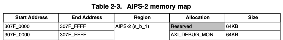
It is reserved! Glad NXP has some non working code in for setting up the QoS, otherwise I will have no idea how to fix it.
Based on the i.MX6's QoS code and u-boot code, there are several things that could be wrong:
- It is not using the highest priority level
- It is not setting the 0x4c register correctly (mask should probably be 0xffffffff, but I have no idea what this register is, it's again not documented in the RM)
- PxP is using elevated QoS level as well, this might compete with EPDC.
However, after fixing all these, it still doesn't seem to be working.
Another point could be looked into, is the memory controller. The QoS value would eventaully reaches the DDR controller, and getting parsed by it. In the DDR controller, there is really only 3 levels or 2 levels, depending on one synthesize time parameter (which I don't know). By default, QoS value > 14 are high level, and anything > 0 are medium level, then 0 is the low level. With this setting, there are 2 possibilities:
- There is only 2 levels in the DDRC. By setting the EPDC to 15 doesn't get it into high level, only medium level, sharing the priority with PxP (if elevated)
- There are 3 levels in DDRC. Then setting EPDC to 15 should get it to the high level.
In any case, it shouldn't matter as long as the EPDC RD channel is at 15 and everything else is at 0 (But I don't have anyway to check that).
But then it just still doesn't work. There are few possible reasons, but from this thread: https://community.nxp.com/t5/i-MX-Processors/Priority-of-the-AXI-bus-in-i-MX7D/m-p/693806, it seems like one simply cannot change the QoS level. These registers are reserved for good reason, and NXP's broken code to change the QoS level just doesn't do anything. (I am not entirely convinced, as NXP seems to claim it fixes the stress test https://lists.denx.de/pipermail/u-boot/2017-August/302437.html To workaroudn the issue, either making sure your application code is not using lot of memory BW while the screen is refreshing, or switch to another processor (like i.MX6).