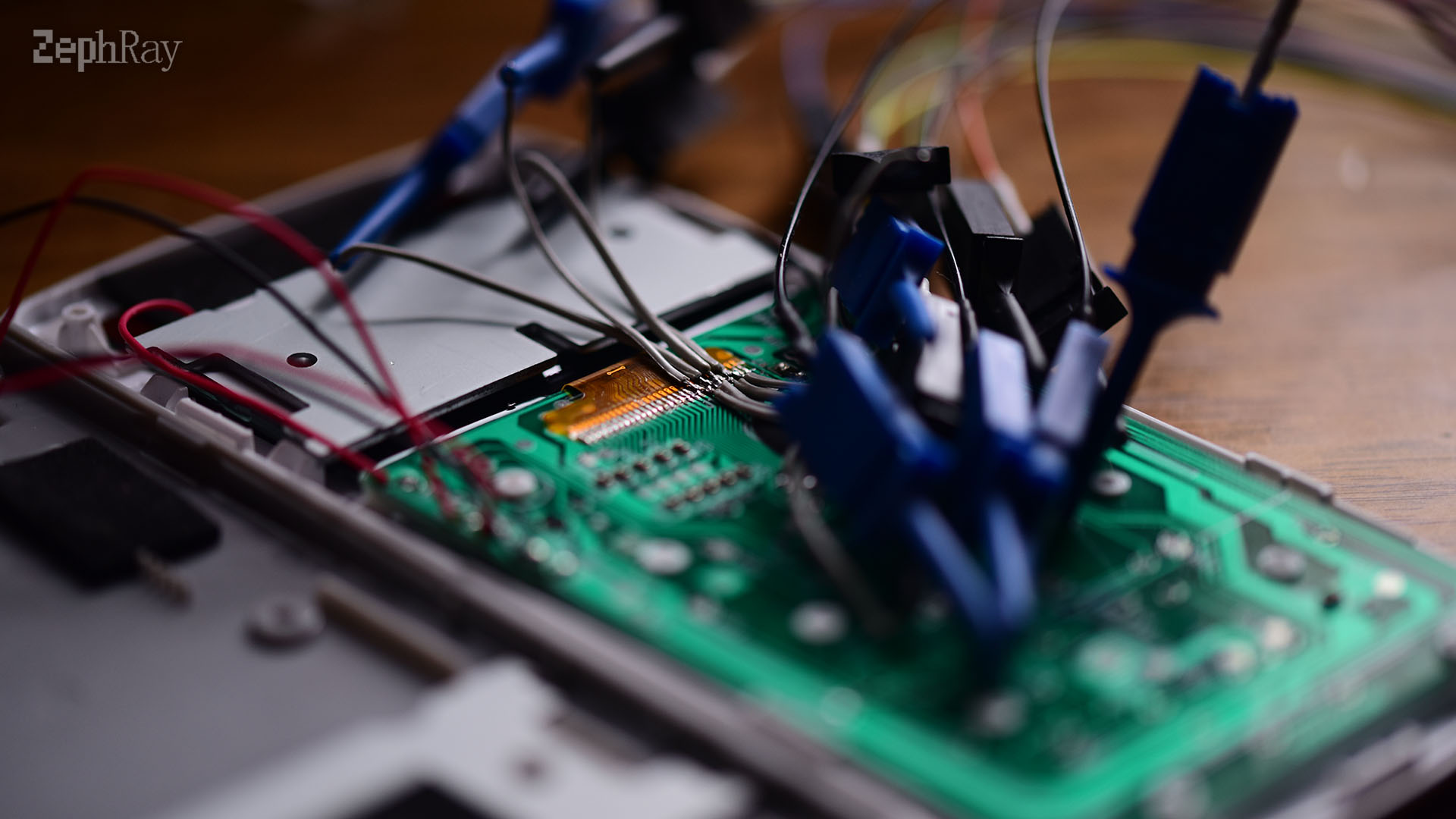
It has been more than a year since the launch of the ClassWiz calculators. And the very first ClassWiz calculator has emerged. Also came with 192x63 high resolution screen and graphical menu. I spent sometime to reverse engineer the protocol of this screen. The protocol seemed weird at first, as the command doesn't match common controllers. I didn't ended up finding the controller, but I was able to guess the instruction use by referring to other controllers.
Basic Information
- Model: FXD1926304-LCD-A0
- Resolution: 192 x 63 + 1 line of icon
- Greyscale: 1bpp (likely)
- Controller: NT10952
Controlling
Initialization
  LCD_WriteCmd(0x88);
  LCD_WriteCmd(0x88);
  LCD_WriteCmd(0x88);
  LCD_WriteCmd(0x88);
  LCD_WriteCmd(0x93);
  LCD_WriteCmd(0xE3);
  LCD_WriteCmd(0xF8);
  LCD_WriteCmd(0x00);
  LCD_WriteCmd(0x81);
  LCD_WriteCmd(0x3C);
  LCD_WriteCmd(0x2E);
  Delay_ms(500);
  LCD_WriteCmd(0x81); // Set Vop
  LCD_WriteCmd(0x27); // Vop
  LCD_WriteCmd(0x82); // Enter partial display mode
  LCD_WriteCmd(0x3F); // Set partial display bias
  LCD_WriteCmd(0x83); // Exit partial display mode
  LCD_WriteCmd(0x10); // Set col address high
  LCD_WriteCmd(0x00); // Set col address low
  LCD_WriteCmd(0xA0); // Set framerate
  LCD_WriteCmd(0xAF); // Turn on display
  LCD_WriteCmd(0xA4); // Disable all pixel on
  LCD_WriteCmd(0xAF); // Turn on display
Setting address
  LCD_WriteCmd(0xB0 | page); // page range 0-7
  LCD_WriteCmd(0x10);
  LCD_WriteCmd(0x00);
Setting contrast
  LCD_WriteCmd(0x81); // Setting Vop
  LCD_WriteCmd(0x20 | contrast); // contrast range 0-0x1F
??
  LCD_WriteCmd(0xE0); // Enter RMW mode
  LCD_WriteCmd(0xB7);
  LCD_WriteCmd(0x1A);
  LCD_WriteCmd(0x0F);
  res1 = LCD_ReadCmd(); //0x00?
  res2 = LCD_ReadCmd(); //0x00?
  LCD_WriteCmd(0x00);
  LCD_WriteCmd(0xEE); // Exit RMW mode
Shutdown
  LCD_WriteCmd(0xAE); // Turn off display
  LCD_WriteCmd(0xA5); // All pixel on
Pinout
- NC
- Vo
- C1P
- C1N
- V1
- C2P
- C2N
- V2
- C3P
- C3N
- V3
- C4P
- C4N
- V4
- VDD
- GND
- D7
- D6
- D5
- D4
- D3
- D2
- D1
- D0
- RD
- WR
- RS
- RST
- CS
- NC
Note: WR and RD are low active, sample on rising edge, RST is low active, RS low = command, RS high = data