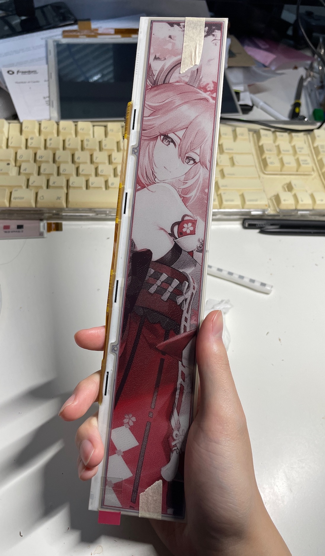
I made a video about this, if you want to watch it: https://www.youtube.com/watch?v=t_YXjM7Keqw
Basically I bought yet another screen without datasheet, so I had to reverse engineer it. I have been doing this for many times over on this blog, but I never really documented it. So this time let me try to summarize some of the common ways how this could be done.
Mainly there are 2 tasks: 1. identify the pinout, 2. identify the chip.
Here are some methods that might work:
If you have a system that this screen:
- If it still powers on you get the pinout and initialization sequence by probing
- If it no longer powers on or refuses to initialize the screen, it might still be possible to RE the system and understand how it might interact with the screen
If you know the pinout, but not the IC:
- If the interface supports read-back, it might be possible to read back the ID register to get the model number
- Brute-force all existing initialization sequence, see if any works
If you know the IC, but not the pinout:
- The pinout can be obtained by simply tracing the wires/ traces on the FPC cable
If you don't know anything or previous methods don't apply:
- Make educated guess of the pinout by looking at the traces/ making measurements and see how they are connected (demonstrated in #LetsDriveLCD 28)
- Try to find similar screens with same number of pins/ similar resolution, they might share the same pinout and IC
- Measure the dimension of the driver IC and compare that with all known ICs, see if there is a match
This time I am using the method of measuring the IC dimension. I am not going to repeat the whole RE process in this blog, if you are interested you may watch the video.
Results:
Pinout
- NC
- GND
- GND
- VDD
- VDD
- VPP
- VCOM
- RST
- MBUSY
- SBUSY
- S2BUSY
- S3BUSY
- SCS
- MCS
- S2CS
- S3CS
- SDA
- SCL
- DC
- BS
- VDD
- VDD
- GND
- GND
- NC

The code is available at https://github.com/zephray/driving-lcds/tree/main/el114tr1