If you’ve played Game Boy Advance non-SP version before, you would probably remember its non-backlit screen design. It’s critical to find the right angle to watch the screen while playing it. The design also makes it impossible to play in the dark, unless you have a flashlight. As a result, in recent years, there have been a lot of backlight mods introduced, to improve the image quality and overall useability. I modded my GBA as well:
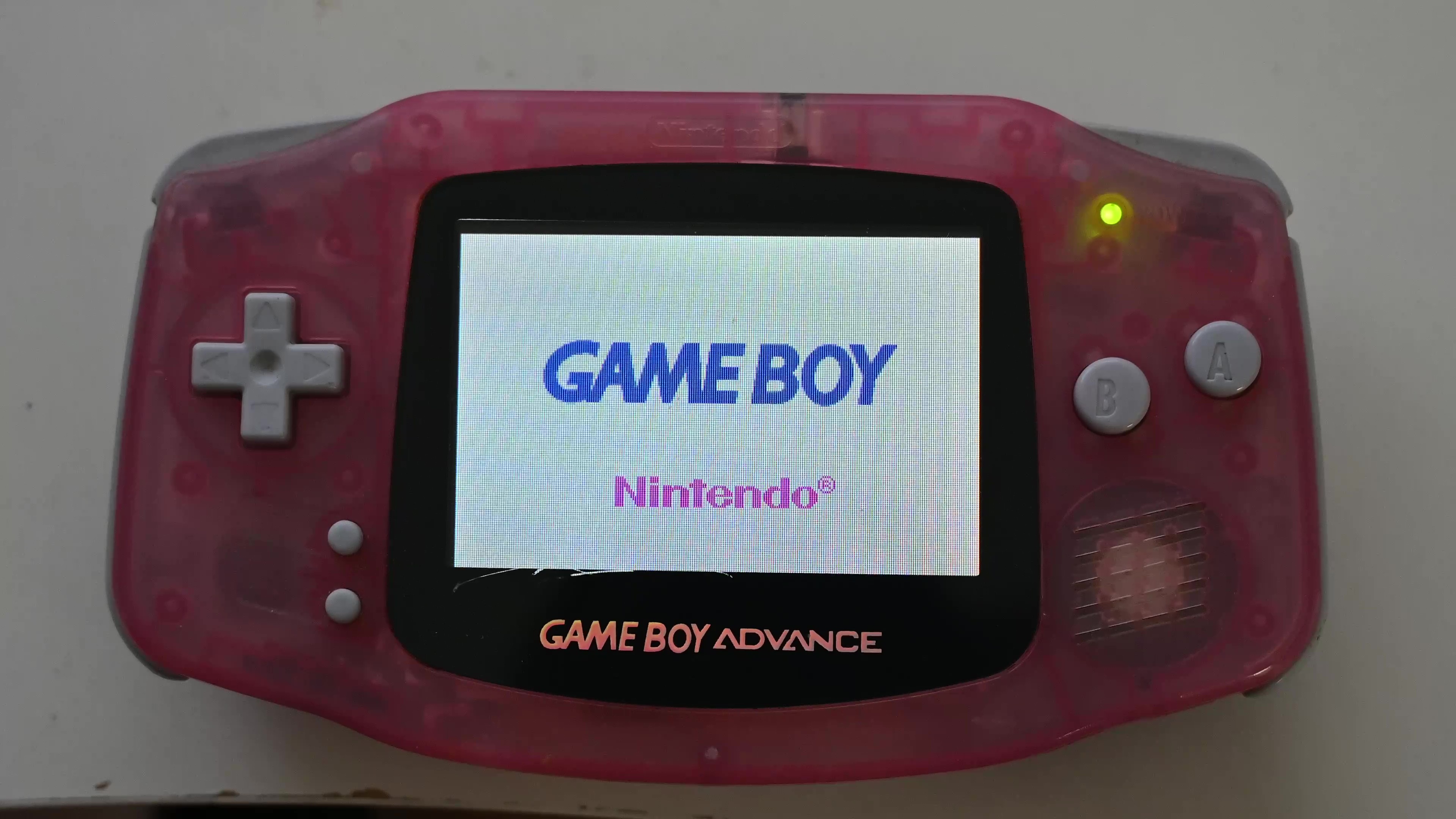
However, instead of upgrading it, would it be possible to downgrade it? Like downgrade to the monochrome non-backlight LCD like those on the original DMG GameBoy or GameBoy Pocket:
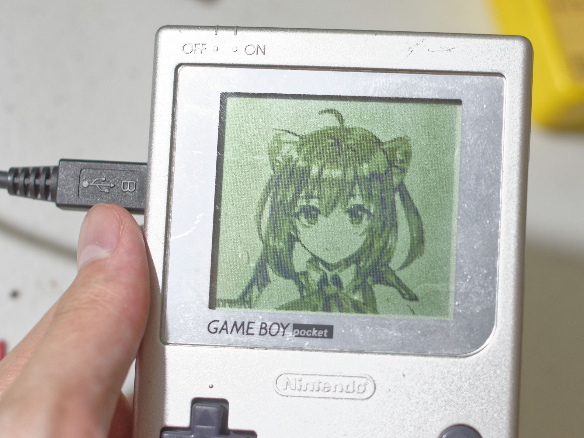
In this blog post, I am going to try such a mod.
The first task is to find screens with matching sizes and resolutions. Surprisingly such screens do exist. With some modifications done to the case, the screen fits into the case nicely. Next onto building the circuit.
Apparently, these screens use different protocols. So directly hooking up the signal won’t work. I will need some chips to convert between them. Normally, a low-power FPGA would be the best choice here. However, when I was building this project earlier this year, all variants of ICE40, MAX10, or SPARTAN 6 7 FPGAs are out of stock. As a result, I decided to give RP2040 another go. With that being said, the plan is to use PIO to capture the LCD output of GBA, then combine with what I had previously, a software sigma-delta modulation grayscale scheme, to convert the color display output from GBA to a grayscale LCD input. Let’s look at the schematics.
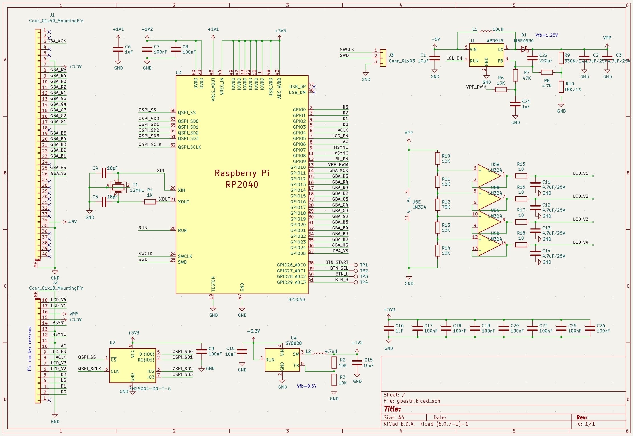
It should be quite straightforward. The Game Boy Advances’ LCD input connector contains the power supply to power the whole board and the video signal that goes directly into RP2040. On the other end, the RP2040’s video output goes directly into the mono LCD. The LCD I am using here doesn’t have an integrated power supply, so I am using a step-up DCDC converter here to generate the required LCD driving supply. You probably remember from GameBoy or similar devices that these screens typically need a dedicated contrast knob. That’s essentially adjusting this voltage. I don’t want to mod the case to add an additional knob, so I added 4 solder pads to allow connecting GBA’s buttons to the microcontroller, and let the microcontroller generate a PWM signal, getting RC filtered to a DC value, then feed into the DCDC converter as part of the feedback voltage.
The LCD also needs several bias voltages. Improper bias voltage could lead to poor contrast and increased cross-talk. I am using a resistor voltage divider to generate the required voltages. Then a basic LM324 opamp to buffer the voltage.
This is about the main components. Import that into the KiCAD PCB editor, place, route, run the DRC, and we are ready to send that to the PCB manufacturer.
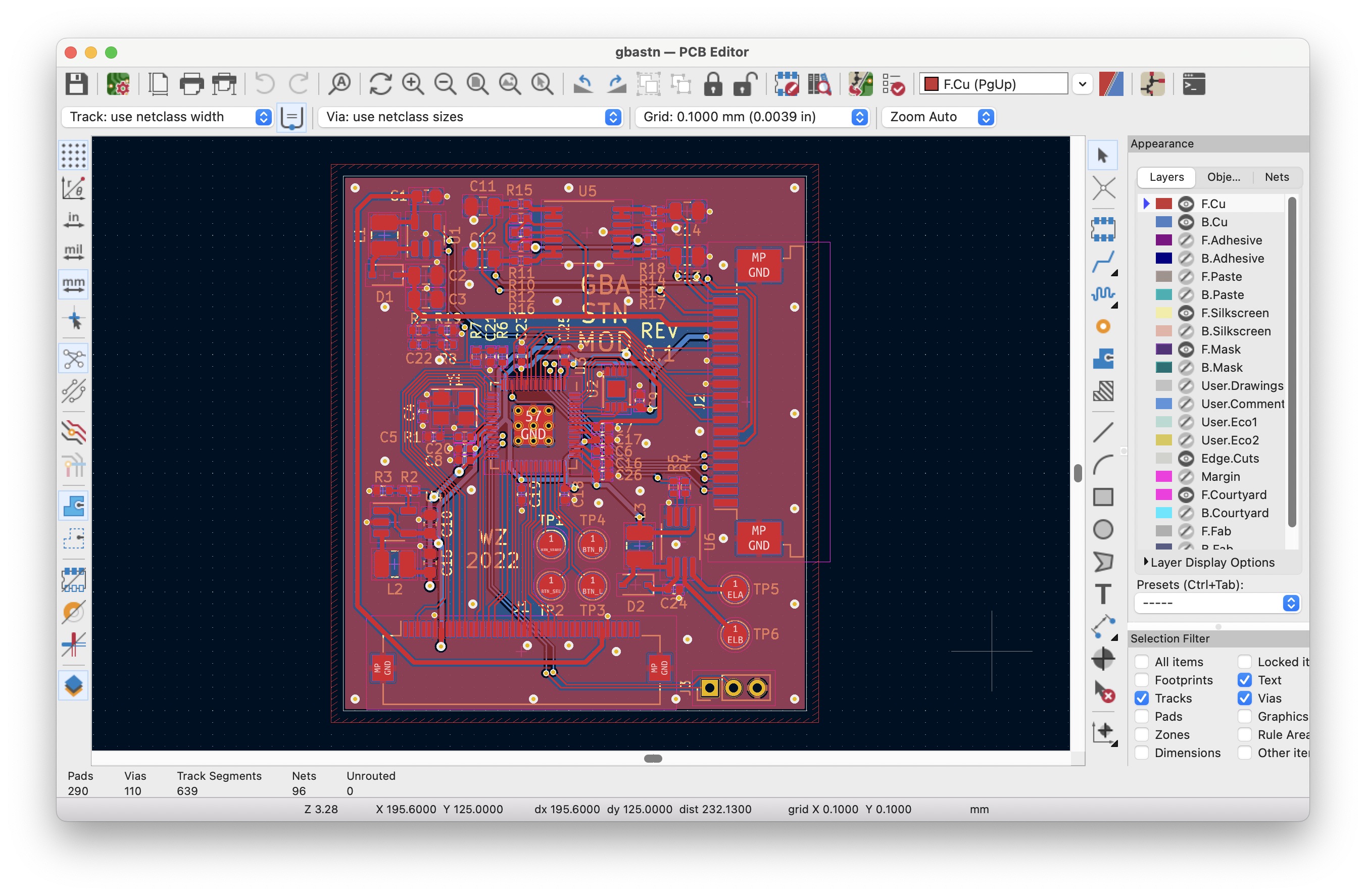
As this is just a simple microcontroller board, everything could be done with just a normal and cheap 2-layer board. Then comes the soldering. Soldering everything and I am ready to test it.
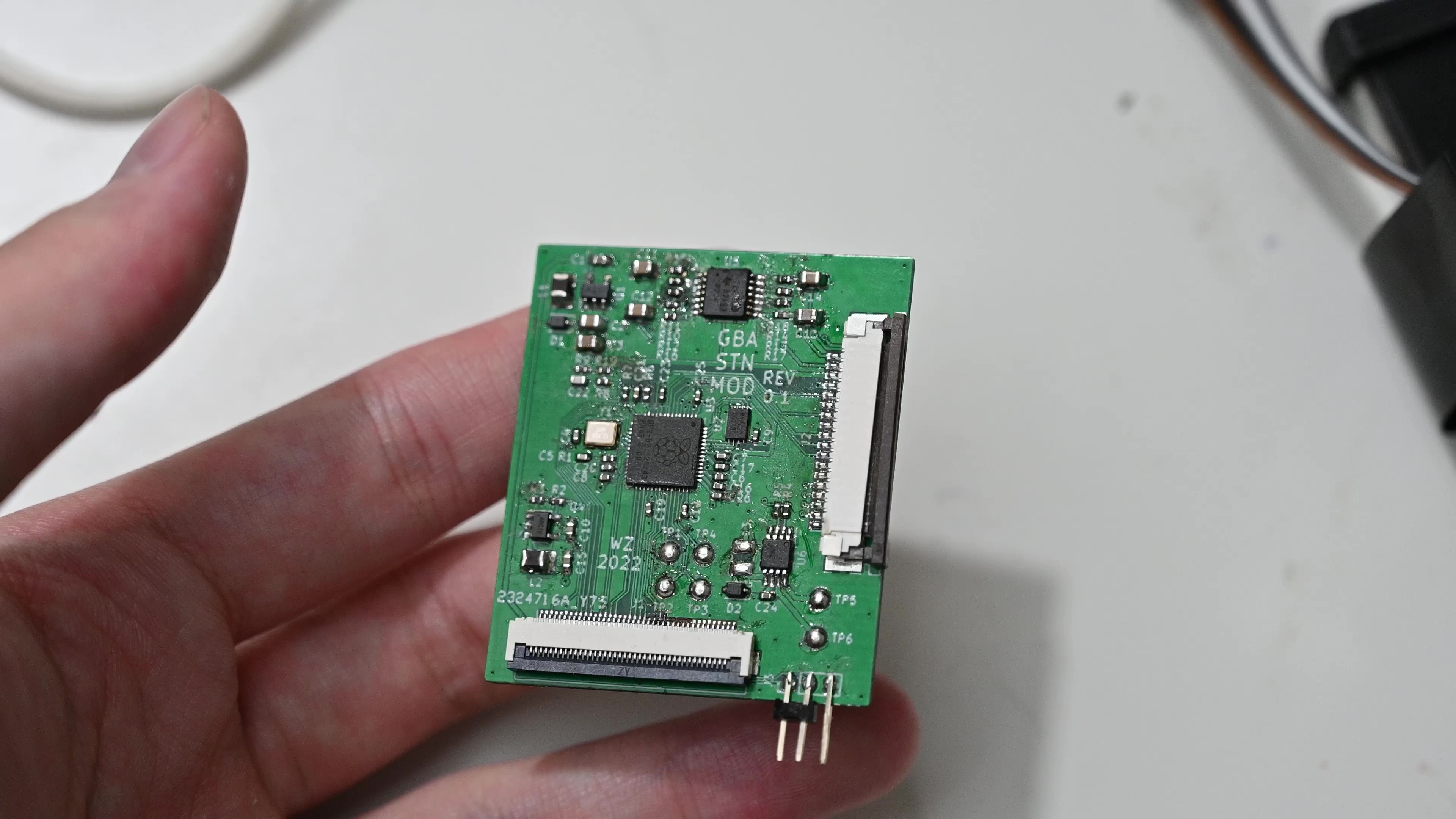
The first is to write a simple program to just enable the screen power supply and check if DCDC works and if I can control the voltage over PWM. Then I can write a program to drive the screen with some static images to test the video output path. I am reusing the code from my previous post.
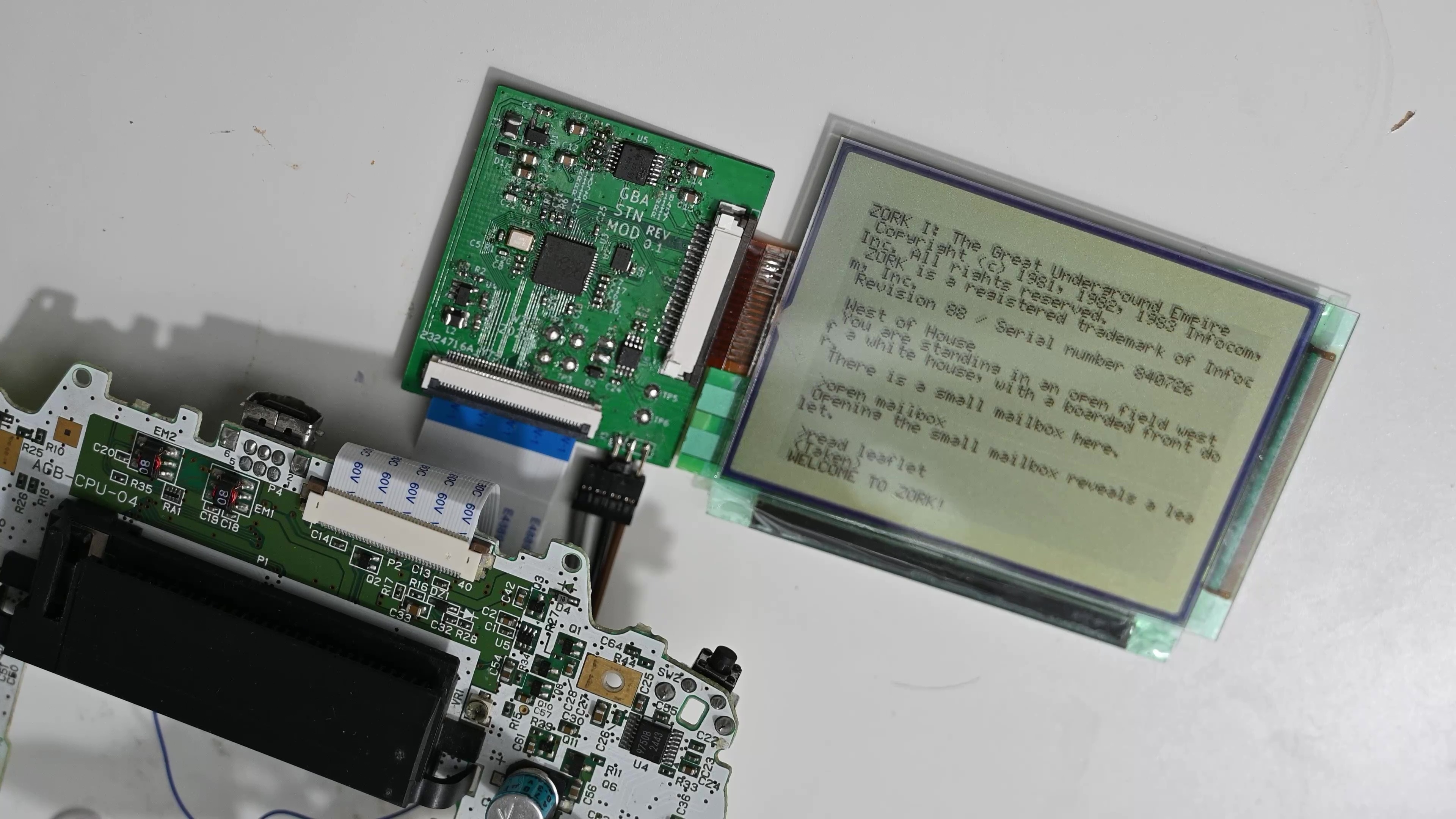
The next task is to capture the video input from GBA. The PIO code is quite simple:
.program vinfsm
    wait 0 gpio 25
    wait 1 gpio 25
.wrap_target
    wait 0 gpio 11
    wait 1 gpio 11
    mov x, ::pins
    in x, 16
.wrap
Wait for the rising edge of vertical sync, then wait for the rising edge of the pixel clock, and sample the input. I wired my hardware wrong, so I have to do another bit reversal to correct the MSB and LSB, but normally one would just use the IN instruction to capture from PINS.
What if I pipe the incoming data directly to the frame buffer?
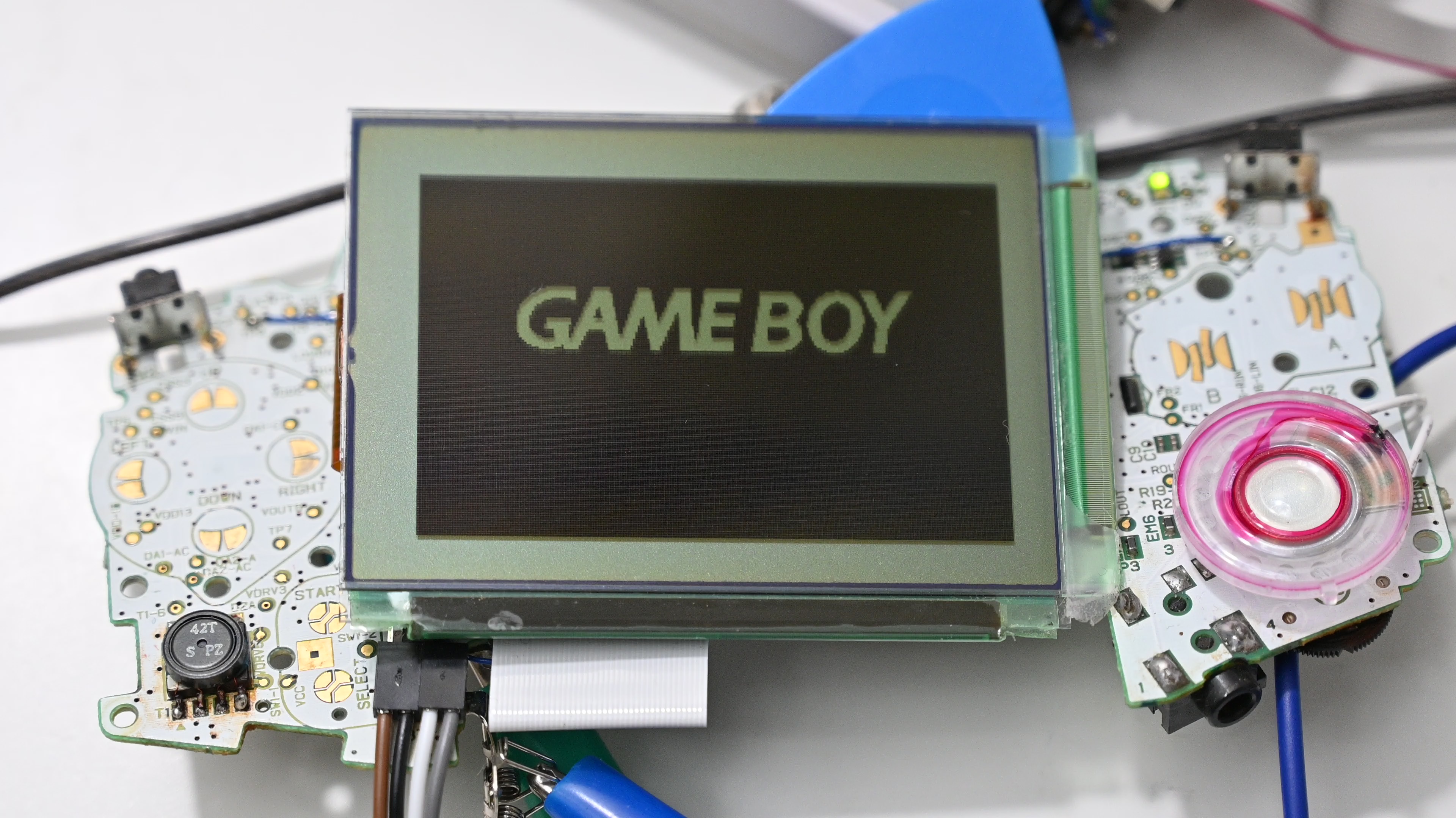
I am already seeing the image, this is good news! GBA gates clock signal during blanking, so I don’t really need to worry about that much. If I can correct the color mapping, then I am good to go.
Color mapping is, however, a slow process. Here is a common RGB to luminance formula:
L = 0.2126 * R + 0.7152 * G + 0.0722 * B
What I need is an integer approximation, that would convert my 0 to 15 R/G/B input value to 0 to 63 luminance value. This is what I ended up with.
L = (9 * R + 30 * G + 3 * B) / 10
However, this is still too slow to calculate at pixel rate, mainly due to the division operation. I had to convert this into a look-up table. Though now if this is pre-calculated, it’s not that important I only use integer operations.
The only missing feature now is adjusting the contrast. I had several solder points for connecting to GBA’s keypad test point. Once they are connected, simply add code to read the button values and adjust the PWM duty cycle.
    if (gpio_get(BTN_START) == false) {
        if (gpio_get(BTN_L) == false) {
            contrast++;
            set_contrast(contrast);
        }
        else if (gpio_get(BTN_R) == false) {
            contrast--;
            set_contrast(contrast);
        }
    }
So this is now finished!
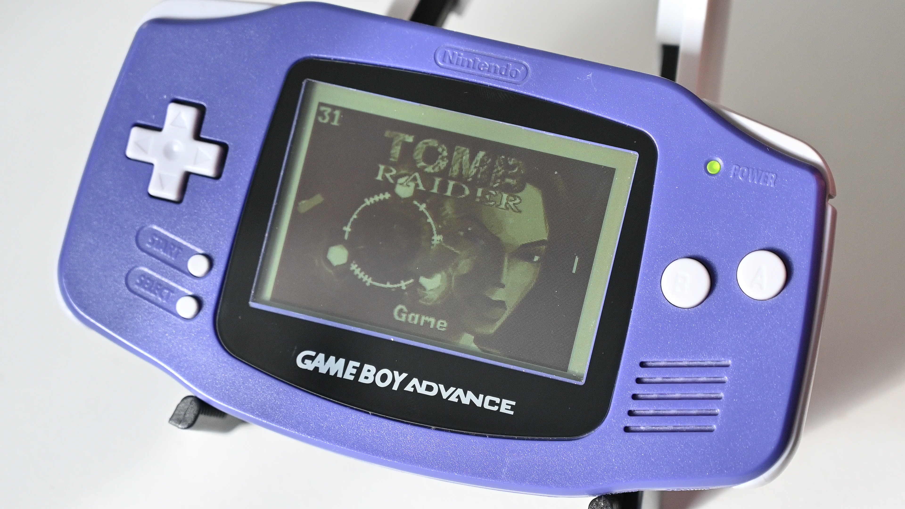
(GBA running OpenLara)
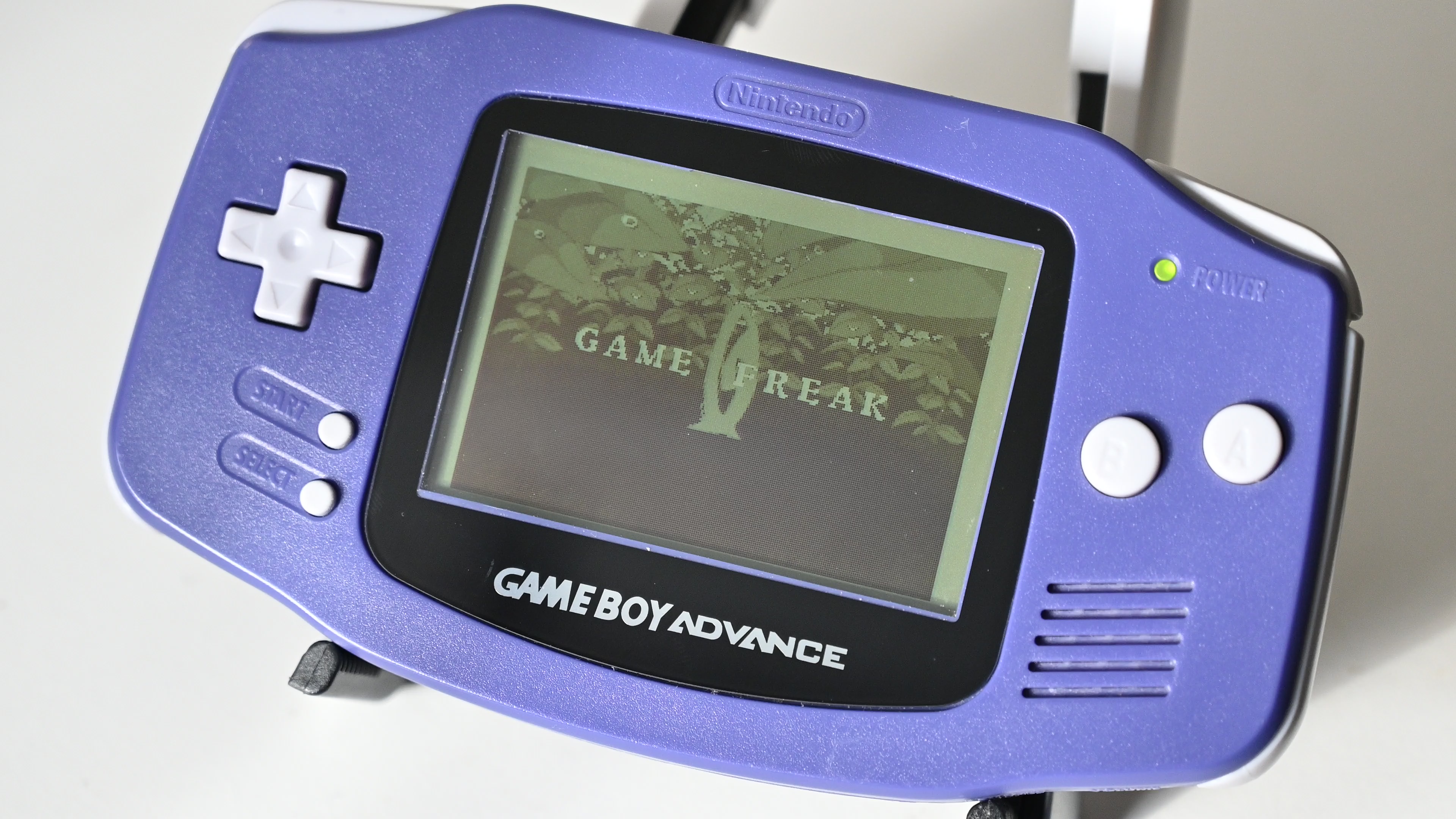
(GBA running Pokemon)
Hope you liked it, and thanks for reading.