Some notes during my own RT board bring up process.
QSPI XIP
QSPI XIP is the recommended way to run the code. Critical sections could be loaded to ITCM if needed. Will compare the performance difference later.
NXP AN12183 gives a good overview about the XIP boot flow, and provided several configurations for other Flash devices. However, the provided configurations were wrong. When using these configurations, the processor would stuck in the Boot ROM area (0x20000) after the image is loaded. The best approach is still to read the datasheet for the specific device used (including all suffix in the model number). Here is my configuration for W25Q32JV:
// Configuration for W25Q32
const flexspi_nor_config_t qspiflash_config = {
    .memConfig =
        {
            .tag                = FLEXSPI_CFG_BLK_TAG,
            .version            = FLEXSPI_CFG_BLK_VERSION,
            .readSampleClkSrc   = kFlexSPIReadSampleClk_LoopbackFromSckPad,
            .csHoldTime         = 3u,
            .csSetupTime        = 3u,
            .columnAddressWidth = 0u,
            .configCmdEnable    = 0u,
            .controllerMiscOption = 0u,
            .deviceType = kFlexSpiDeviceType_SerialNOR,
            .sflashPadType = kSerialFlash_4Pads,
            .serialClkFreq = kFlexSpiSerialClk_30MHz,
            .lutCustomSeqEnable = 0u,
            .sflashA1Size  = 4u * 1024u * 1024u,
            .lookupTable =
                {
                    // Read LUTs
                    FLEXSPI_LUT_SEQ(CMD_SDR, FLEXSPI_1PAD, 0xEB, RADDR_SDR, FLEXSPI_4PAD, 0x18),
                    FLEXSPI_LUT_SEQ(MODE8_SDR, FLEXSPI_4PAD, 0xFF, DUMMY_SDR, FLEXSPI_4PAD, 0x04),
                    FLEXSPI_LUT_SEQ(READ_SDR, FLEXSPI_4PAD, 0x04, STOP, 0, 0),
                },
        },
    .pageSize           = 256u,
    .sectorSize         = 4u * 1024u,
    .blockSize          = 64u * 1024u,
    .isUniformBlockSize = false,
};
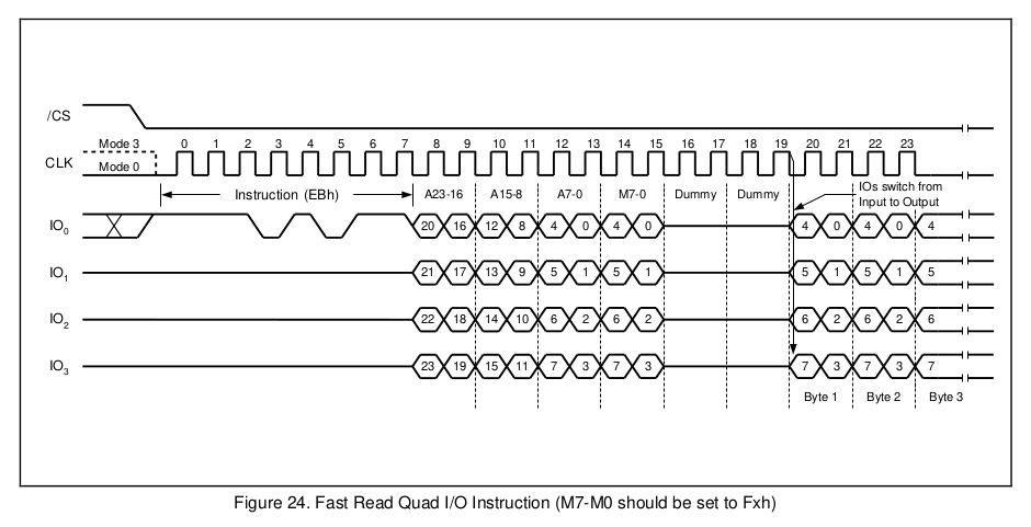
The read LUT should match the timing diagram given in the datasheet:

The RADDR (row address) is 24 bits (0x18), there is a 8-bit Mode (MODE8), needs to be 0xFx, followed by 4 dummy cycles (DUMMY), finally it reads data.
Note: my board design didn't leave the DQS pad floating, so I had to loopback from SCK. For optimal performance, leave the DQS pad floating, and use DQS loopback.
