 I promised that there would be an update about the USB, here it is. This update would only talk about the USB 2.0 Host on the Pano Logic G1 devices with ISP1760 USB host controller, so it is probably not applicapable to other platforms. The goal here is to write a set of RTL and software stack, so it is possible to use USB HID joystick/ gamepad and USB mass storage devices on the Pano G1. Speed would not be the concern here.
Hardware Connections
On the Pano G1, an USB 2.0 high-speed host controller (Phillips ISP1760) is connected to the FPGA via 16-bit parallel memory bus. To mitigate one of the controller’s errata, an USB high speed hub (SMSC USB2513) is connected to one of the downstream port of the controller, and all user accessible ports are connected to the USB hub.
Overall Architecture
Though it might be possible to write a FSM to implement some basics of the USB host protocol stack, it is just not very practical. (Device side might be more practical, though). The solution I have here is to continue use the PicoRV32 soft-core processor on the FPGA. The host controller would be mapped to PicoRV32’s memory space as MMIO, then software driver and protocol stack can run on the PicoRV32. When needed, certain outputs can be achieved by using MMIO GPIO (for example, output the currently pressed keys). Hopefully, debugging software would be much easier than debugging hardware.
Generally, there would be several layers. The bottom part is called as the HCD (Host Controller Driver), which is specific to particular hardware, like the controller chip being used. Then it comes the HD (Host Driver), this is the part handles device enumeration and USB Hub communication, this layer is no longer specific to the platform. Higher than that is the class driver, as name suggests this is specific to a device class, for example, HID class or audio class. The driver might be generic to the whole class, or it might just support one of few specific USB devices. Higher than that, usually it is operating system, or in our case, user application.
In conclusion, there are 5 things I need to do:
- Write the RTL to interface ISP1760 with PicoRV32
- Port or write the HCD for ISP1760
- Port some appropriate host driver over
- Port or write the class driver for HID gamepad and mass storage devices
- Write some application code to use the driver
Let’s discuss all these parts.
MMIO interface
This is the easiest part. It is a pretty standard parallel async MMIO interface. Though there are DMA modes, but I am not going to support them anyway so forget about these. The address space is 64KB, so there should be 16 address lines. As the data bus width is 16 bit, and the access is always half-word aligned, the lowest line is omitted, leaving 15 address lines. However, here it has A[17:1], in total of 17 address lines. According to the datasheet, the upper 2 bits are used to denote the currently accessing page, and the device allows opening multiple pages at the same time… Sounds like that of SDRAM. As I said speed wouldn’t be the concern here, so they are never used in my code. Otherwise it’s fairly standard. Just to make it even simpler, I didn’t to the bitwidth conversion logic, the low 16bits of the data bus is connected to the low 16bits of the CPU, and high 16bits are left unconnected. Thus it is occupying twice the address space as it should, and all addresses should be shifted by one to compensate the wasted bitwidth.
HUBs
Before I talk about the USB protocol stack, I want to talk more about USB hubs. The architecture of Pano G1’s USB is basically, full of hubs. In the hardware, there is one USB Hub chip, but that’s not all.
According to the EHCI (Enhanced Host Controller Interface) specification (the standard USB 2.0 host controller specification), a USB 2.0 high speed host controller would be only able to communicate with high speed devices. No full speed or low speed devices are possible here. To implement an USB host that is compatible to both types of devices, one would need to incorporate an additional OHCI (Open Host Controller Interface) or UHCI (Universal Host Controller Interface) compatible controller into the system, then use an analog switch to switch to them when the connected device is a low-speed or full-speed one.
Well, this sounds, stupid. Why would one need to put two controller chips in the system for one USB port and switch between them? Is it possible to design one controller that is capable handling both type of devices?
Well it is possible, and such controllers do exist. It is called as TDI controller in the Linux kernel, TDI refers the company TransDimension, which developed such kind of controller. The company later was renamed to Oxford semiconductor, acquired by PLX technology, and then acquired by Broadcom. The general idea is using a transaction-translator (TT) from the USB 2.0 specification (but not part of EHCI specification). The user can plug in USB devices with different speeds on the same hub, however to maximize the throughput, the USB hub should always communicate with the upstream using high speed mode. This means the hub must have some way to interface with LS or HS devices and transfer the LS/HS data through a HS port. This is exactly what needed: the ECHI controller could only provide one HS port. TT could adapt a LS or FS device to a HS port. TDI controller is basically a standard EHCI controller with a TT, as well as few additional registers to control the embedded TT.
Or, without modifying the controller, one can just connect a standard USB 2.0 hub to the EHCI controller, and the hub would handle that nicely. This is the way Philips did that: in the ISP1760, there is one integrated Philips ISP1520 USB 2.0 Hub, directly connected to the host controller inside the chip. I am not sure how this connection is done internally, but it doesn’t matter from driver’s perspective, it is just one hub connected to one of the DFP (downstream facing port). Now there is in total of 2 hubs in the device.
But there could be a third one: the root hub. In the device manager of a Windows PC, one can see these root hubs. For example, this is a screenshot of the device manager on my PC:
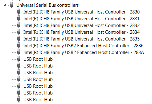
What are these? Is there always one embedded hub in the controller? Not really. The host driver sometimes needs to control the port. For example, turn on or off the power supply of a specific port, or reset a specific port. For USB hubs, they are implemented as control packets sent to the USB hub, the hub would receive these packs and function accordingly. But to control ports on an EHCI compatible controller, one would need to use MMIO to modify certain registers to accomplish the same thing. From the driver interface perspective, this is inconvenient: there would be two different interfaces to do the same thing. As a result, generally in the HCD (host controller driver), there would be some code to emulate a hub: it would intercept control packets sent to endpoint 0, reports itself as a USB hub, and write values to MMIO when certain control packets are being received. So there would be a third hub in the system. Imagine our poor packet would have to go through at least three hubs before it can reach the other end… And our protocol stack must be able to handle multiple layers of hub as well.
Though luckily, on ISP1760, the third layer is optional: the ISP1760 HC (host controller) only has one DFP, and it is always connected to the integrated ISP1520 hub. There is generally no reason for the software to control this DFP after it is running, so we might just hardcode these register configurations. Then the integrated ISP1520 would become the root hub. But then the system still has 2 hubs to go through.
Host Driver
The next step would be HCD. But as the HCD highly depends on the host driver, I need to decide which host driver to use first. Generally, this is about picking a USB host stack to use. I really don’t want to waste my time reinventing another wheel here, not talking about the difficulties of debugging many things at the same time.
The first one I found is called the TinyUSB. Unfortunately, as its README points out, it does not support cascading hubs. I assume this is something limited by their architecture, and probably not something that can be easily supported without refactoring a lot of code. But their code is very clean, it should be relatively easy to understand and modify if I have to. The second project I found is the stack written for the Arduino USB host shield. (The one from Circuits @ Home). It does support hub, and it does contain many useful class drivers (especially for USB gamepads, it has driver for dualshock 3, it has driver for xbox 360 controller etc. Though later it turns out, I don’t really need them). The main issue here is that, in my opinion, the code is not very clean compared to TinyUSB. I am not saying that I can write better or cleaner code than he does, I just want to save my time from reading other’s code as I am not a very good reader.
The third, well, is the Linux. (And uClinux) It turns out Analog Devices once made an USB host expansion board with ISP1760 for their (our) Blackfin DSP. There were two drivers, one by Philips, another from community. The latter is merged into Linux mainline. At first I thought it would be great to play with it with Blackfin first: I would be able to write and debug my bare-metal driver on the Blackfin, with the help of a JTAG debugger. But after a quick search in the office, we no longer have that USB expansion board in our office (I found other two types of USB expansion board, but they are not helpful to me). The Linux driver might be useful as a reference in the future, but I am not going to try to port that USB stack to bare-metal myself. It might take more time than just writing one.
By the way, can I just run Linux on the Pano G1 and use its ISP1760 driver? The answer is no. With 256KB or on-board non-volatile storage, there is simply no way I can put a USB capable linux kernel there. I cannot load it from Ethernet as there is no Ethernet IP for Pano. The only viable way is put some bootloader like u-boot there, which can load the kernel from a USB drive and then boot the Linux kernel. But if I have such a bootloader that can access USB, why would I need Linux then? I would just add my application code to the bootloader.
Talk about the bootloader, I guess the most famous one would be u-boot. The u-boot has USB support. What about using its USB stack? Taking USB out of u-boot and use it standalone should be easier than adding RV32IC support to the u-boot. The USB support of u-boot was taken from a very ancient version of Linux, and developed on top of that since then. As a bootloader, it favors simplicity over performance. The result is extremely clean and simple code, with a very minimalistic interface to HCD and class driver. Though it does not have support for ISP1760, it does have support for EHCI (ISP1760 claimed itself to be EHCI compatible), and support of a lot of other controllers for me to reference. It only has two class driver, one for keyboard (HID), and another for mass storage. That’s almost exactly what I need. That’s the code I am looking for. To actually use u-boot’s USB code… Copy the usb.c, usb.h, appropriate HCD, and needed class drivers to your project, and enjoy. Note by the time of writing, they are adapting to a new driver model that all USB drivers should conform. I thought I don’t need that, and I have no use of a lot of extra xHCI (eXtensible Host Controller Interface) support code, so I just used the code from u-boot 2009. Note code from 2009 does contain several bugs in the USB code. I fixed them, and found the master has fixed them already much earlier. You can find the code with my patches at github.com/zephray/phUSB.
HCD
HCD (Host Controller Driver) is what communicate with the USB controller chip. It’s generally specific to one chip or one platform. Unfortunately u-boot doesn’t have built-in support for ISP1760. But at least it has EHCI support. Normally, if the USB host controller is EHCI compatible, then I should be able to directly use the EHCI driver, because that’s what EHCI means, a unified interface between driver and USB controller chip. This is the case on most of the EHCI compatible controllers, for example, USB controller on NXP’s i.MX SoC. Well, ISP1760 claimed to be an EHCI compatible controller, can I use the standard EHCI driver? No. ISP1760 made a big change, the ISP1760 is a bus slave, means it cannot request data from the memory. This is one key feature of ISP1760, at the same time makes it very different from EHCI. It does have many EHCI registers, but not fully compliant to EHCI. It also has more its own registers. As a conclusion, EHCI specification and EHCI driver would be nice references to have, but I would better write my own driver.
In u-boot’s USB host stack model, the HCD only need to do two things: transfer data and emulate root hub. In our case, the second is optional. Let’s take a look at the interface between HCD and host driver:
int usb_lowlevel_init(void);

int usb_lowlevel_stop(void);

int submit_bulk_msg(struct usb_device *dev, unsigned long pipe, void *buffer, int transfer_len);

int submit_control_msg(struct usb_device *dev, unsigned long pipe, void *buffer, int transfer_len, struct devrequest *setup);

int submit_int_msg(struct usb_device *dev, unsigned long pipe, void *buffer, int transfer_len, int interval);

void usb_event_poll(void);
Initialization, reset, submit three types of messages, and event poll if no interrupt is possible. All the functions except interrupt transfer are blocking, they should return when finished. This means there would be no queue, or list, things like that, greatly simplify the design of both HCD and host driver, with the cost of performance. The Linux driver, on the other hand, uses mostly non-blocking functions. Things are done asynchronously, for higher performance. The next task is just read the datasheet, read the application code, and write the code based on these documents. When in doubt, take a guess mark as TODO, or reference the Linux driver. Testing the code is mostly seeing if it can finish the device enumeration without error.
Class Driver
The class driver is the driver that would interface with the plugged in USB device (except hubs). In my case, I need two class drivers, one for HID, and another for mass storage. Luckily, u-boot has both, though the HID one is limited to keyboard and mouse.
HID gamepad
HID actually refers to a very wide range of devices, including keyboard, mouse, gamepad, joystick, control wheel, remote controller, etc. The class driver I am going to write is only for gamepads. Though there are many different types of HID, but they are all input devices, they return fixed length information to the host, through HID report. In the case of keyboard and mouse, the report format is consistent across all HID-compliant keyboards and mice. Thus, a generic driver can be written that would work for all keyboards and mice. However this is not the case for other devices. Different HIDs might need to report completely different items, making it impossible to design a report format that would work for all other HIDs. What they did instead was introduced a HID report descriptor. That descriptor contains the field definition for the report. By the way, keyboard and mouse also has their own HID report descriptor as well, but there is not much need to parse them as they are almost always compatible.
So here comes the choice: To write a HID gamepad driver, one may hardcode the report field definition for various different HID-compliant gamepads; one may also actually write a parser to parse the HID descriptor, making the driver generic to all HID-compliant gamepads. The stack for Arduino USB host shield I mentioned before chose the first approach; they created a whole bunch of drivers for different gamepads as they have different report format. Windows and Linux, on the other hand, obviously picked the second way. The issue of second way is that, the driver would only know how many buttons there are in the report, but it would have no idea about what these buttons are (is it a circle or cross). As a result, it is often required to do some button mapping when first time playing a game on PC. (You may notice this is not the case for Xbox controllers, this is because Xbox controllers are not HID-compliant, they are always hardcoded.)
As there are way too many different USB gamepads on the market, there would be no way for me to support them all. So I went with the second approach as well.
To make my life easier, I am not going to make a fully HID-compliant parser, it just needs to work with parts that are relevant and used in the common controllers. This turns out to be rather straightforward. Things are organized in collections, means there are some hierarchies in the descriptor, but they may be ignored as far as I am concerned. The general flow of processing is as follows:
void usb_gp_parse_descriptor(uint8_t *descriptor, uint32_t descriptor_length) {
    uint8_t item_type;
    uint8_t item_length;
    uint32_t item_value;
    uint32_t i = 0;

    while(i < descriptor_length) {
        item_type = descriptor[i] & 0xfc;
        item_length = descriptor[i] & 0x03;
        item_length = (item_length == 3) ? (4) : (item_length); // 3 means 4
        i += 1;
        item_value = 0;
        for (int bc = 0; bc < 4; bc++)
            if (item_length > bc)
                item_value |= (uint32_t)descriptor[i + bc] << (8 * bc);

        switch (item_type) {

        }
        i += item_length;
    }
    return;
}
The basic unit inside a HID descriptor is an item. Each item would have its type and value. Multiple items may have the same type value. The type is always 6 bits long. The value can be 1 byte, 2 bytes, or 4bytes long. The parser can be viewed as a state machine, some items would change its state, and its state would affect how it interprets the item. The job of the descriptor is to describe the bit or byte fields of the report, so the most important item would be the item that describes a single field. That item is the type 0x80 (input) item. However the value of the input item only indicates if the field is valid or not (for padding), the length and definition are defined by global states. This could saves several bytes when describing a lot of same or similar fields. This is also probably the reason of keeping global states.
In my parser, inputs are divided into 2 categories, binary controls, and analog controls. Buttons and Dpad are generally binary values, analog sticks, analog triggers, and accelerometer values are all analog values. The parser would save the bit offset of each binary value in the report, and byte offset of each analog values in the report.
Finally, in the report parser, it would use the offsets gathered from HID descriptor to extract values from the report. It then put these values into an array, to be used later by the user application.
The complete parser can be found at: https://github.com/zephray/phUSB/blob/master/class_driver/usb_gamepad.c
Mass Storage Devices
Well, I don’t have much to say about this, because the u-boot’s driver works fine for me, I didn’t pay too much attention to that.
Conclusion
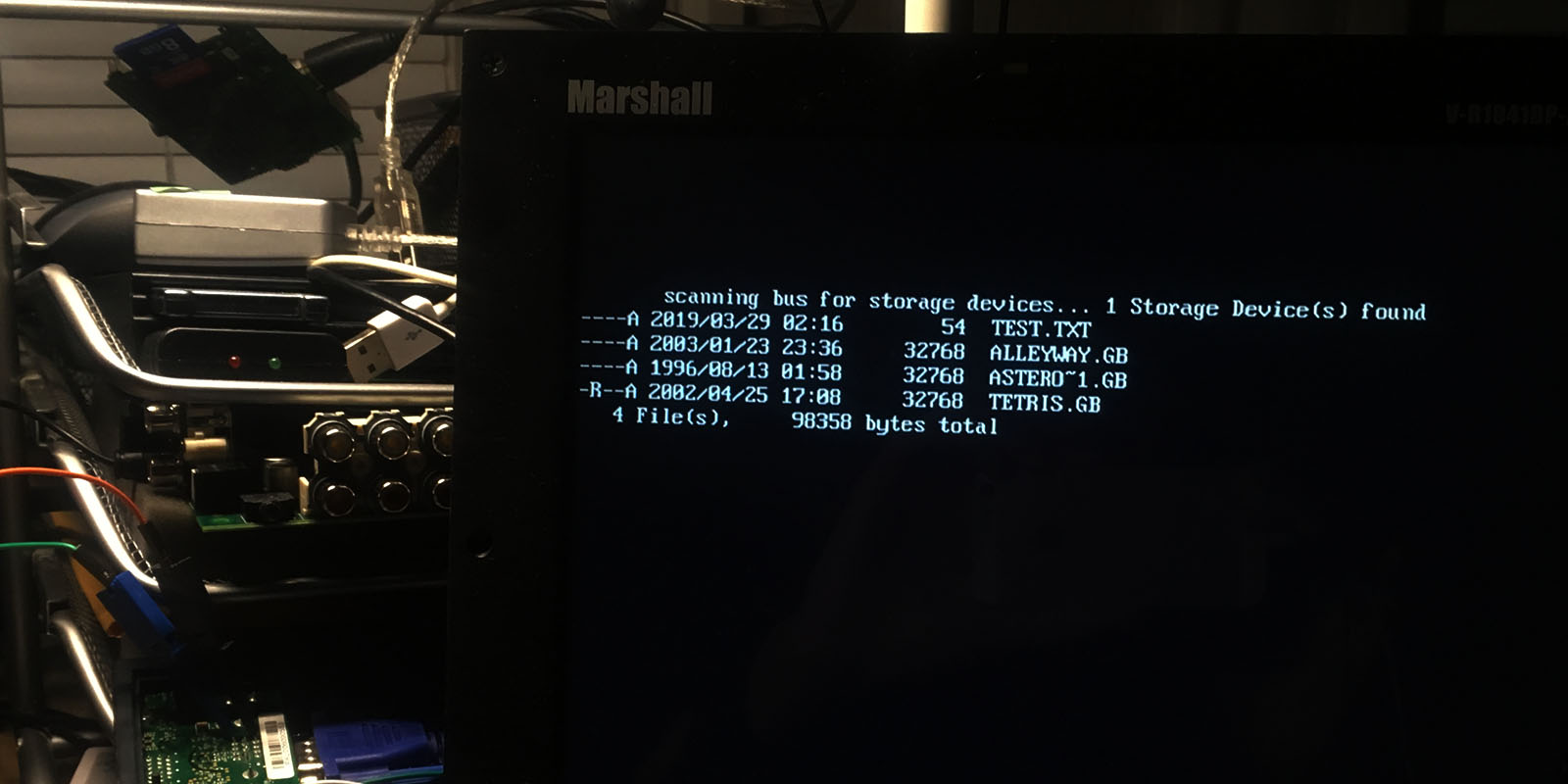
In conclusion, the USB is working. The debugging experience reminds me when I first started learning MCUs: there is no JTAG, no trace, and no stack dump. All I have is serial print. I don’t have access to the actual signals: they are inside the Pano box and it is generally hard to connect a probe to a LQFP pin. Each time I want to try new version of program I need to download the new firmware into Flash, rather than just loading into RAM (well this is much better than UV-erased PROM though). All these just slow the process down, but overall that’s still something doable.
Wish list
Currently there is no Ethernet support for Pano G1 devices. It would be much better if we can load the code using protocol like TFPT via Ethernet. It is going to make debugging so much easier.