Introduction
I recently bought few Plannar EL640.480-AM series panels. They are monochrome 10.4" 640x480 TFEL panels with an STN LCD interface. It is similar to DPI (sometimes called RGB), the screen is timed with HVSync signals, and needs to be continuously refreshed. But, as a monochrome screen, the pixel is 1bpp, so the data bus transmits multiple pixels at a time. These screens are also dual-scan: there are two "raster beams" at the same time, one refresh from the top of the screen, the other one refreshes from the middle of the screen. They are supposed to be refreshed at 120 Hz.
This creates some interesting challenges: It expects to be driving with an STN LCD controller. However, where can I find one?
- There used to be dedicated graphics controllers such as NM128 or CT65530 that could drive STN LCDs directly. But they have been long obsolete.
- ARM SoCs from the early 2000s typically has an LCD controller that is capable of driving STN LCDs. However many of these SoCs are also being deprecated or obsolete.
- There used to display controller chips that could convert VGA into STN LCD signals. But I don't know any specific models. I suspect they are also being deprecated.
If not using dedicated hardware (and I am not too interested in buying one anyway), there are several alternative ways to drive it:
- Use a really fast microcontroller with a large SRAM to Bit-Bang the GPIO to generate the video signal.
- Use a CPLD/FPGA to generate the timing
I have used both methods before. The first method:
The second method:
I am going to use the microcontroller way this time again. But this time I am going to use the RP2040, which has a very powerful IO engine called PIO. We will see how it would help us with driving the screen and offload the CPU core.
Claimer: The methods described here are provided as-is. Use at your own risk.
I am new to RP2040, this is the first time I use the PIO. So the program provided here is likely not optimal.
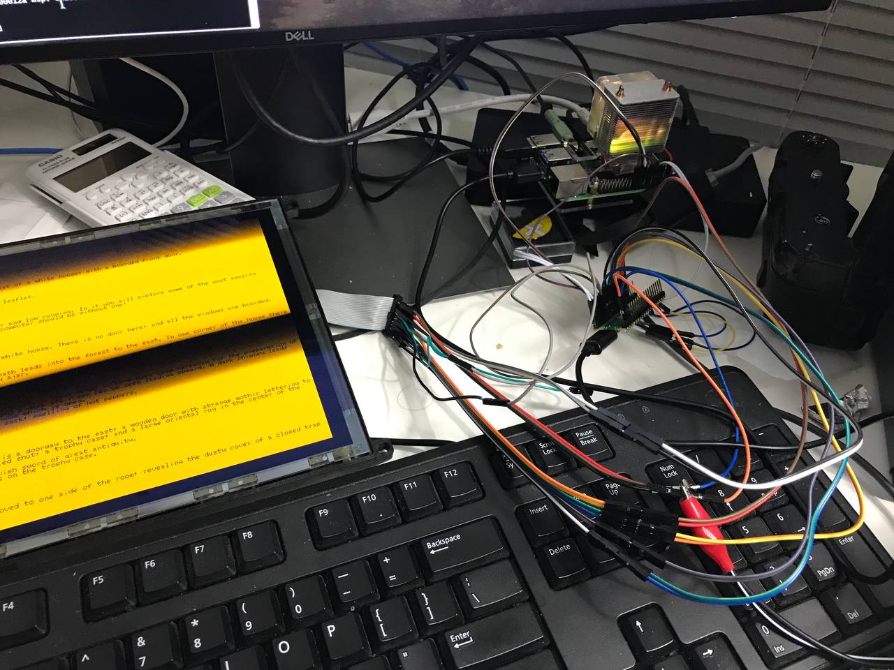
Fully bit-banged version
I started with a fully bit-banged version because this is the most straightforward way to implement the protocol.
The code:
static void frame(void) {
    uint8_t *rdptr_ud = framebuf;
    uint8_t *rdptr_ld = framebuf + SCR_STRIDE * SCR_HEIGHT / 2;
    for (int y = 0; y < SCR_HEIGHT / 2; y++) {
        for (int x = 0; x < SCR_STRIDE; x++) {
            uint8_t du = *rdptr_ud++;
            uint8_t dl = *rdptr_ld++;
            for (int b = 0; b < 2; b++) {
                gpio_put(PIXCLK_PIN, 1);
                gpio_put(LD0_PIN, dl & 0x08);
                gpio_put(LD1_PIN, dl & 0x04);
                gpio_put(LD2_PIN, dl & 0x02);
                gpio_put(LD3_PIN, dl & 0x01);
                gpio_put(UD0_PIN, du & 0x08);
                gpio_put(UD1_PIN, du & 0x04);
                gpio_put(UD2_PIN, du & 0x02);
                gpio_put(UD3_PIN, du & 0x01);
                gpio_put(PIXCLK_PIN, 0);
                dl >>= 4;
                du >>= 4;
            }
        }
        gpio_put(HSYNC_PIN, 1);
        gpio_put(VSYNC_PIN, (y == 0) ? 1 : 0);
        delay(15);
        gpio_put(HSYNC_PIN, 0);
        delay(5);
        gpio_put(VSYNC_PIN, 0);
    }
}
Because the screen needs to be refreshed continuously, the main function would look like this:
    while (1) {
        frame();
    }
This eats up all the CPU cycles, so the MCU wouldn't be able to do anything else. Even worse, the MCU should not service any interrupts, as the screen is sensitive to the timing.
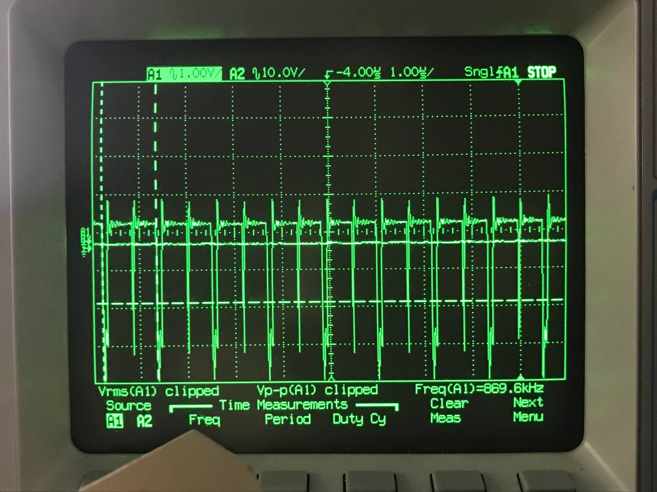
This is also pretty slow. At 125 MHz system clock, I got:
- 44 Hz VSync
- 11.5 kHz HSync
- 870 kHz Pixel Clock
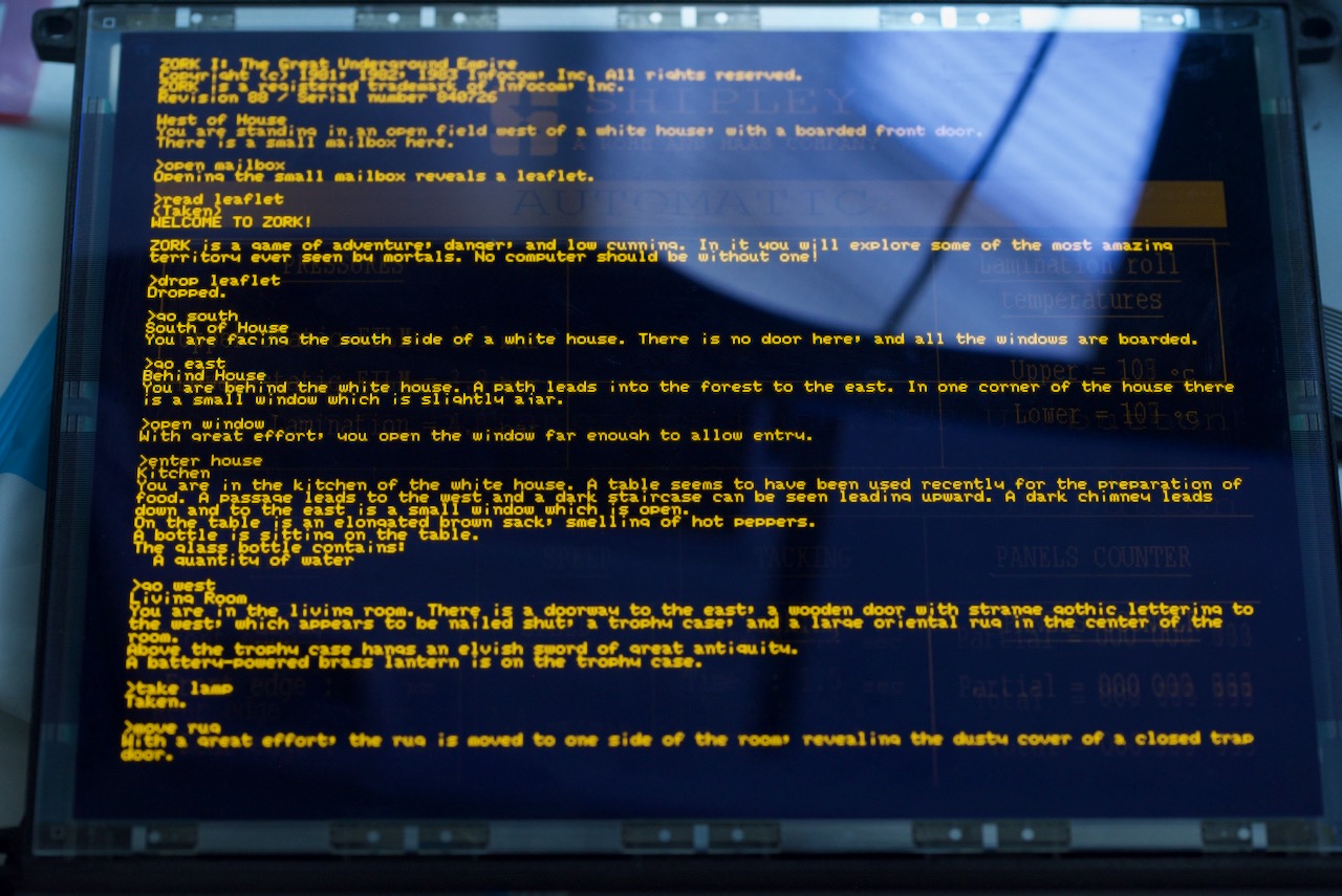
The screen works, but the flicking is quite noticeable. As a proof-of-concept, this shows the screen works, so I can move on.
Using PIO to send data
Sending parallel data over GPIO by banging individual lines as in the previous example is quite slow. Fortunately, this could be easily offloaded by using the PIO.
As the first step, I will only replace the data sending part with PIO. That is 2 4-bit synchronous parallel buses. By using the auto pulling feature and sideset pin feature, it could be easily implemented as a simple PIO SM:
.program el_udata
.side_set 1
.wrap_target
    out pins, 4     side 1
    nop             side 0
.wrap
Each PIO SM (state machine) is capable of handling one FIFO (datastream). Here the screen has two raster beams, so two state machines would be needed. I am calling them EL_UDATA_SM and EL_LDATA_SM The catch is, two state-machines must be strictly synchronous to each other. We will see how it would be implemented.
Put the sync issues aside, just to replace the GPIO with PIO, the frame() function would look like this:
static void frame(void) {
    uint32_t *rdptr_ud = (uint32_t *)framebuf;
    uint32_t *rdptr_ld = (uint32_t *)(framebuf + SCR_STRIDE * SCR_HEIGHT / 2);
    for (int y = 0; y < SCR_HEIGHT / 2; y++) {
        for (int x = 0; x < SCR_STRIDE / 4; x++) {
            uint32_t du = *rdptr_ud++;
            uint32_t dl = *rdptr_ld++;
            elsm_put(du, dl);
        }
        elsm_wait();
        gpio_put(HSYNC_PIN, 1);
        gpio_put(VSYNC_PIN, (y == 0) ? 1 : 0);
        delay(15);
        gpio_put(HSYNC_PIN, 0);
        delay(5);
        gpio_put(VSYNC_PIN, 0);
    }
}
The elsm_put() function puts the data into the PIO FIFO and lets the PIO sends the data, and the elsm_wait() functions waits for the PIO to finish sending the data. Which are implemented as follows:
static inline void elsm_put(uint32_t ud, uint32_t ld) {
    while (pio_sm_is_tx_fifo_full(el_pio, EL_UDATA_SM));
    *(volatile uint32_t *)&el_pio->txf[EL_LDATA_SM] = ld;
    *(volatile uint32_t *)&el_pio->txf[EL_UDATA_SM] = ud;
}

static inline void elsm_wait(void) {
    uint32_t sm_stall_mask = 1u << (EL_UDATA_SM + PIO_FDEBUG_TXSTALL_LSB);
    el_pio->fdebug = sm_stall_mask;
    while (!(el_pio->fdebug & sm_stall_mask));
}
However, this code won't work. Checking only for one SM for full or stall is not an issue here. If both SMs are guaranteed to be in sync, then checking only one SM is sufficient. However, this code does not guarantee the sync between two SMs. Considering at the line start, both SMs are being stalled because the FIFO is empty. The elsm_put function writes to the EL_LDATA_SM, but before it writes to the EL_UDATA_SM, the clock edge of PIO clock comes, then the EL_UDATA_SM would advance its state, but not EL_LDATA_SM. In such cases, they are out of sync.
The solution is to stop the SM at first, pre-fill the FIFO and then start both SM in sync:
    uint32_t *rdptr_ud = (uint32_t *)framebuf;
    uint32_t *rdptr_ld = (uint32_t *)(framebuf + SCR_STRIDE * SCR_HEIGHT / 2);
    for (int y = 0; y < SCR_HEIGHT / 2; y++) {
        pio_sm_set_enabled(el_pio, EL_UDATA_SM, false);
        pio_sm_set_enabled(el_pio, EL_LDATA_SM, false);
        // prefill FIFO
        elsm_put(*rdptr_ud++, *rdptr_ld++);
        // start SM
        pio_enable_sm_mask_in_sync(el_pio, (1u << EL_UDATA_SM) | (1u << EL_LDATA_SM));
        // loop filling FIFO
        for (int x = 1; x < SCR_STRIDE / 4; x++) {
            uint32_t du = *rdptr_ud++;
            uint32_t dl = *rdptr_ld++;
            elsm_put(du, dl);
        }
        elsm_wait();
        gpio_put(HSYNC_PIN, 1);
        gpio_put(VSYNC_PIN, (y == 0) ? 1 : 0);
        delay(15);
        gpio_put(HSYNC_PIN, 0);
        delay(5);
        gpio_put(VSYNC_PIN, 0);
    }
This would produce a glitch-free image.
Following are the additional PIO setup code
static void elsm_init() {
    static uint udata_offset, ldata_offset;

    for (int i = 0; i < 4; i++) {
        pio_gpio_init(el_pio, UD0_PIN + i);
        pio_gpio_init(el_pio, LD0_PIN + i);
    }
    pio_gpio_init(el_pio, PIXCLK_PIN);
    pio_sm_set_consecutive_pindirs(el_pio, EL_UDATA_SM, UD0_PIN, 4, true);
    pio_sm_set_consecutive_pindirs(el_pio, EL_UDATA_SM, PIXCLK_PIN, 1, true);
    pio_sm_set_consecutive_pindirs(el_pio, EL_LDATA_SM, LD0_PIN, 4, true);

    udata_offset = pio_add_program(el_pio, &el_udata_program);
    ldata_offset = pio_add_program(el_pio, &el_ldata_program);

    int cycles_per_pclk = 2;
    float div = clock_get_hz(clk_sys) / (EL_TARGET_PIXCLK * cycles_per_pclk);

    pio_sm_config cu = el_udata_program_get_default_config(udata_offset);
    sm_config_set_sideset_pins(&cu, PIXCLK_PIN);
    sm_config_set_out_pins(&cu, UD0_PIN, 4);
    sm_config_set_fifo_join(&cu, PIO_FIFO_JOIN_TX);
    sm_config_set_out_shift(&cu, true, true, 32);
    sm_config_set_clkdiv(&cu, div);
    pio_sm_init(el_pio, EL_UDATA_SM, udata_offset, &cu);

    pio_sm_config cl = el_ldata_program_get_default_config(ldata_offset);
    sm_config_set_out_pins(&cl, LD0_PIN, 4);
    sm_config_set_fifo_join(&cl, PIO_FIFO_JOIN_TX);
    sm_config_set_out_shift(&cl, true, true, 32);
    sm_config_set_clkdiv(&cl, div);
    pio_sm_init(el_pio, EL_LDATA_SM, ldata_offset, &cl);
}
Using PIO + DMA to send data
In the previous example, though now the MCU could push out pixels at a much faster rate, it doesn't necessarily free up the CPU time. The core is still busy with writing data into the PIO and waits for it to finish. A better way is to use the DMA to do this.
To just first test the idea of using DMA, use the blocking mode transfer first, so it would be a drop-in replacement of the current copy loop. Use the following code to setup 2 DMA channels that would be used:
static void el_dma_init() {
    el_udma_chan = dma_claim_unused_channel(true);
    dma_channel_config cu = dma_channel_get_default_config(el_udma_chan);
    channel_config_set_transfer_data_size(&cu, DMA_SIZE_32);
    channel_config_set_read_increment(&cu, true);
    channel_config_set_write_increment(&cu, false);
    channel_config_set_dreq(&cu, DREQ_PIO0_TX0 + EL_UDATA_SM);

    dma_channel_configure(el_udma_chan, &cu, &el_pio->txf[EL_UDATA_SM], NULL, SCR_STRIDE / 4, false);

    el_ldma_chan = dma_claim_unused_channel(true);
    dma_channel_config cl = dma_channel_get_default_config(el_ldma_chan);
    channel_config_set_transfer_data_size(&cl, DMA_SIZE_32);
    channel_config_set_read_increment(&cl, true);
    channel_config_set_write_increment(&cl, false);
    channel_config_set_dreq(&cl, DREQ_PIO0_TX0 + EL_LDATA_SM);

    dma_channel_configure(el_ldma_chan, &cl, &el_pio->txf[EL_LDATA_SM], NULL, SCR_STRIDE / 4, false);
}
Then the copy loop in the frame() function could be replaced with DMA function calls:
static void frame(void) {
    uint32_t *rdptr_ud = (uint32_t *)framebuf;
    uint32_t *rdptr_ld = (uint32_t *)(framebuf + SCR_STRIDE * SCR_HEIGHT / 2);
    dma_channel_set_read_addr(el_udma_chan, rdptr_ud, false);
    dma_channel_set_read_addr(el_ldma_chan, rdptr_ld, false);

    for (int y = 0; y < SCR_HEIGHT / 2; y++) {
        pio_sm_set_enabled(el_pio, EL_UDATA_SM, false);
        pio_sm_set_enabled(el_pio, EL_LDATA_SM, false);
        // Setup DMA
        dma_channel_start(el_udma_chan);
        dma_channel_start(el_ldma_chan);
        // start SM
        pio_enable_sm_mask_in_sync(el_pio, (1u << EL_UDATA_SM) | (1u << EL_LDATA_SM));
        // Increment addr
        // Wait for finish
        dma_channel_wait_for_finish_blocking(el_udma_chan);
        dma_channel_wait_for_finish_blocking(el_ldma_chan);
        // Wait for SM to finish
        elsm_wait();
        gpio_put(HSYNC_PIN, 1);
        gpio_put(VSYNC_PIN, (y == 0) ? 1 : 0);
        delay(15);
        gpio_put(HSYNC_PIN, 0);
        delay(5);
        gpio_put(VSYNC_PIN, 0);
    }
}
Now the CPU is no longer copying the data, it is being done by the DMA. However the CPU is not freed up yet: it is still always waiting for the DMA to finish, and the main loop is still a while(1) frame(). Nothing else could be done other than waiting for the DMA.
So instead of letting the CPU waiting all the time, interrupts can be used to allow the CPU to do other things while the DMA and PIO are busy sending stuff.
Modify the handler into such 3 functions:
static int el_cur_y = 0;

static void el_dma_start_line() {
    pio_sm_set_enabled(el_pio, EL_UDATA_SM, false);
    pio_sm_set_enabled(el_pio, EL_LDATA_SM, false);
    // Setup DMA
    dma_channel_start(el_udma_chan);
    dma_channel_start(el_ldma_chan);
    // start SM
    pio_enable_sm_mask_in_sync(el_pio, (1u << EL_UDATA_SM) | (1u << EL_LDATA_SM));
}

static void el_dma_start_frame() {
    uint32_t *rdptr_ud = (uint32_t *)framebuf;
    uint32_t *rdptr_ld = (uint32_t *)(framebuf + SCR_STRIDE * SCR_HEIGHT / 2);
    dma_channel_set_read_addr(el_udma_chan, rdptr_ud, false);
    dma_channel_set_read_addr(el_ldma_chan, rdptr_ld, false);
    el_dma_start_line();
}

static void el_dma_handler() {
    dma_hw->ints0 = 1u << el_udma_chan;

    elsm_wait();
    gpio_put(HSYNC_PIN, 1);
    gpio_put(VSYNC_PIN, (el_cur_y == 0) ? 1 : 0);
    delay(15);
    gpio_put(HSYNC_PIN, 0);
    delay(5);
    gpio_put(VSYNC_PIN, 0);
    el_cur_y ++;
    if (el_cur_y == SCR_HEIGHT / 2) {
        // End of frame, reset
        el_cur_y = 0;
        el_dma_start_frame();
    }
    else {
        el_dma_start_line();
    }
}
Each time when the DMA finishes transferring one line, the el_dma_handler function would be called, generate the HVSync signals, and configure the DMA to start the next line.
Add the following code to the DMA initialization code before to enable the interrupt:
    dma_channel_set_irq0_enabled(el_udma_chan, true);

    irq_set_exclusive_handler(DMA_IRQ_0, el_dma_handler);
    irq_set_enabled(DMA_IRQ_0, true);
Finally, remove the frame() call in the main loop, and call the el_dma_start_frame() before the main loop to kick off the DMA for the first frame. Now, try to add things like LED blinking in the main, note how it would work along with the DMA + PIO taking care of the EL display refresh in the background.
To see how much CPU is free for other tasks, it is possible to toggle a GPIO pin when in the interrupt, so non-interrupt time would be free time.
It turns out, the output duty cycle is about 48%, which means the CPU load is 48%. There is still around 50% left for other tasks. Just keep in mind this does not include the overhead for interrupt processing (context switching), so actual useable CPU time would be less.
Using DMA + PIO for both data and sync
50% CPU usage compared to 270% CPU usage (if I want it to refresh at 120 Hz) at first is a pretty good improvement, but still not perfect:
- The CPU is still using a busy-loop delay loop to control the timing of HVsync.
- The CPU still needs to use a busy-loop to wait for the PIO to finish sending data. The DMA only interrupts when the data have been pushed into FIFO, but not when the PIO has depleted the FIFO. There is one TX FIFO non-full interrupt, but not empty interrupt.
- The screen is sensitive to the timing difference. If for some reason CPU didn't service the interrupt exactly on time, some artifacts might be visible.
The solution is to use the PIO to handle HVsync as well. Luckily, the PIO does have support for down counters, so I will use this capability to let it count the coordination and generate the HVsync signal.
The idea is that the SMs would not only just output data, but also count down in both the X and Y direction, so it could generate both HVsync signals. When it reaches the end of the frame, it generates an interrupt to the CPU.
The code is as follows, I am using 1 IRQ bit to sync between them:
; UDATA SM handles UD0-3, PCLK, and VSYNC
; PCLK is mapped to SIDE, VSYNC is mapped to SET, and UD0-3 are mapped to OUT
.program el_udata
.side_set 1
    irq set 5 side 0
    mov x, isr side 0
loop_first_line:
    out pins, 4 side 1
    jmp x-- loop_first_line side 0
end_first_line:
    set pins, 1 [6] side 0
    set pins, 0 [9] side 0
line_start:
    irq set 5 side 0
    mov x, isr side 0
loop:
    out pins, 4 side 1 ; Output 4 bit data
    jmp x-- loop side 0 ; Loop until x hits 0, then wait for next line
loop_end:
    nop [15] side 0
    jmp y-- line_start side 0
    ; end of frame, signal CPU
    irq wait 1 side 0


; LDATA SM handles LD0-3 and HSYNC
; HSYNC is mapped to SET, and LD0-3 are mapped to OUT
.program el_ldata
    ; Signal UDATA SM to start outputting data
    mov x, isr
    wait irq 5
loop:
    out pins, 4
    jmp x-- loop
    ; toggle Hsync and signal Vsync SM
    set pins, 1 [5]
    set pins, 0 [10]
For the Y counter, it only needs to count down once, so it is fine to just load it directly into the register. However, the X counter needs to be reloaded every line, so a seperate register needs to hold the initial value. The values can be loaded in the C code:
static void el_sm_load_reg(uint sm, enum pio_src_dest dst, uint32_t val) {
    pio_sm_put_blocking(el_pio, sm, val);
    pio_sm_exec(el_pio, sm, pio_encode_pull(false, false));
    pio_sm_exec(el_pio, sm, pio_encode_out(dst, 32));
}

...
    // Load configuration values
    el_sm_load_reg(EL_UDATA_SM, pio_y, SCR_REFRESH_LINES - 2);
    el_sm_load_reg(EL_UDATA_SM, pio_isr, SCR_LINE_TRANSFERS - 1);
    el_sm_load_reg(EL_LDATA_SM, pio_isr, SCR_LINE_TRANSFERS - 1);
...
PIO interrupt also needs to be configured. In the code, I was using irq wait 1 to signal the main CPU, so the IRQ flag 0 should be routed to the main CPU:
    el_pio->inte0 = PIO_IRQ0_INTE_SM1_BITS;
    irq_set_exclusive_handler(PIO0_IRQ_0, el_pio_irq_handler);
    irq_set_enabled(PIO0_IRQ_0, true);
It is kind of confusing that the register definition makes it sounds like it is routing the SM1 interrupt to the PIO0_IRQ_0, but it is just routing PIO IRQ flag 1 to the CPU. It is not bound to the SM1. For example, here I am using SM0 to generate IRQ flag 1.
Now the interrupt handler can be further simpified:
static void el_pio_irq_handler() {
    uint8_t *framebuf = frame_state ? framebuf_bp0 : framebuf_bp1;
    frame_state = !frame_state;
    uint32_t *rdptr_ud = (uint32_t *)framebuf;
    uint32_t *rdptr_ld = (uint32_t *)(framebuf + SCR_STRIDE * SCR_HEIGHT / 2);
    dma_channel_set_read_addr(el_udma_chan, rdptr_ud, false);
    dma_channel_set_read_addr(el_ldma_chan, rdptr_ld, false);

    pio_sm_set_enabled(el_pio, EL_UDATA_SM, false);
    pio_sm_set_enabled(el_pio, EL_LDATA_SM, false);

    pio_sm_clear_fifos(el_pio, EL_UDATA_SM);
    pio_sm_clear_fifos(el_pio, EL_LDATA_SM);

    pio_sm_restart(el_pio, EL_UDATA_SM);
    pio_sm_restart(el_pio, EL_LDATA_SM);

    // Load configuration values
    el_sm_load_reg(EL_UDATA_SM, pio_y, SCR_REFRESH_LINES - 2);
    el_sm_load_reg(EL_UDATA_SM, pio_isr, SCR_LINE_TRANSFERS - 1);
    el_sm_load_reg(EL_LDATA_SM, pio_isr, SCR_LINE_TRANSFERS - 1);

    // Setup DMA
    dma_channel_start(el_udma_chan);
    dma_channel_start(el_ldma_chan);
    // Clear IRQ flag
    el_pio->irq = 0x02;
    // start SM
    pio_enable_sm_mask_in_sync(el_pio,
            (1u << EL_UDATA_SM) | (1u << EL_LDATA_SM));
}
Now the interrupt is only fired at 120Hz and only takes 750ns to run at 125MHz clock frequency. This translates to a CPU load of only 0.009% (750ns * 120Hz / 1e9ns)! This is a huge improvement, at the cost of few additional SM instructions.
Note that it is actually possible to eliminate this interrupt as well. The PIO and DMA could push pixels out automatically without any CPU intervention. However, I am not doing it here, because precise Vsync interrupts are quite useful. I could switch framebuffers here without any tearing effects. This is also critical to implement FRC for greyscales.
Conclusion
This blog shows how to leverage the PIO found on RP2040 to drive a not-so-common type of display. Combined with the large SRAM found on the RP2040, this is quite usable. As I mentioned before I am a beginner who just started learning RP2040, the method presented here is almost certainly doesn't make full use of the PIO and could be further optimized. All code provided is licensed under MIT license, take them if they turn out to be helpful for your project. Thanks for reading.
Full source code available at: https://gist.github.com/zephray/cb9340d278ed2ab6eb47398d2ca29b3c