Introduction
VGA and CGA are the display standard used on IBM-PC, initially designed for CRT. This time I am going to try to drive these monitors using FPGA.
I am just getting started learning FPGA, so these might not be the best practice.
VGA
Before getting into CGA, let me try VGA first, which has more information online. There are 5 signals in the VGA, HVsync + RGB analog input. The following is the timing diagram:
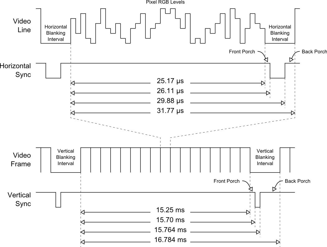
In order to generate a VGA signal, there are 2 part: 1. generate horizontal and vertical sync 2. generate pixel at the correct time. So here I have the basic system diagram.
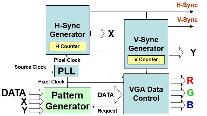
Now I could start.
First I need a PLL for pixel clock. In Quartus II select Tools → MegaWizard Plug-in Manager, select Create a new custom megafunction variation, then choose PLL. Input Clock is 50MHz, and divide by 2 to get 25MHz. Then I could add these to the top level:
vgapll u2 (
.inclk0(CLOCK_50),
.c0(V_REFCLK)
);
Now I have a 25MHz V_REFCLK.
Then I could start working on the sync signals. Before that, define the parameters necessary:
// Horizontal
parameter H_FRONT = 16; // Front porch
parameter H_SYNC  = 96; // Sync
parameter H_BACK  = 48; // Back porch
parameter H_ACT   = 640;// Active pixels
parameter H_BLANK = H_FRONT+H_SYNC+H_BACK; // Total blanking
parameter H_TOTAL = H_FRONT+H_SYNC+H_BACK+H_ACT; // Total length

// Vertical
parameter V_FRONT = 11; // Front porch
parameter V_SYNC  = 2;  // Sync
parameter V_BACK  = 31; // Back porch
parameter V_ACT   = 480;// Active lines
parameter V_BLANK = V_FRONT+V_SYNC+V_BACK; // Total blanking
parameter V_TOTAL = V_FRONT+V_SYNC+V_BACK+V_ACT; // Total length
Then the sync generator is simple to implement:
always @(posedge V_REFCLK or negedge RST_N)
begin
  if(!RST_N)
  begin
    H_Cont <= 0;
    VGA_HS <= 1;
  end
  else
    if(H_Cont<H_TOTAL)
      H_Cont <= H_Cont + 1'b1;
        else
      H_Cont <= 0;
      if(H_Cont==H_FRONT-1)
        VGA_HS <= 1'b0;
      if(H_Cont==H_FRONT+H_SYNC-1)
        VGA_HS <= 1'b1;
  end
end

always@(posedge VGA_HS or negedge RST_N)
begin
  if(!RST_N)
  begin
    V_Cont <= 0;
    VGA_VS <= 1;
  end
  else
  begin
    if(V_Cont<V_TOTAL)
      V_Cont <= V_Cont+1'b1;
    else
      V_Cont <= 0;
    if(V_Cont==V_FRONT-1)
      VGA_VS <= 1'b0;
    if(V_Cont==V_FRONT+V_SYNC-1)
      VGA_VS <= 1'b1;
  end
end
And the signals for the pixel generator:
assign N_X = (H_Cont>=H_BLANK) ? H_Cont-H_BLANK : 11'h0;
assign N_Y = (V_Cont>=V_BLANK) ? V_Cont-V_BLANK : 11'h0;
assign N_Address = N_Y*H_ACT+N_X;
assign N_Enable = ((H_Cont>=H_BLANK && H_Cont<H_TOTAL)&&
                   (V_Cont>=V_BLANK && V_Cont<V_TOTAL));
To keep things simple let me start from RGB332 / 8 bit per pixel. Define a 8 bit color and assign the signals:
assign VGA_R[9:7] = N_Color[7:5];
assign VGA_R[6:4] = N_Color[7:5];
assign VGA_R[3:1] = N_Color[7:5];

assign VGA_G[9:7] = N_Color[4:2];
assign VGA_G[6:4] = N_Color[4:2];
assign VGA_G[3:1] = N_Color[4:2];

assign VGA_B[9:8] = N_Color[1:0];
assign VGA_B[7:6] = N_Color[1:0];
assign VGA_B[5:4] = N_Color[1:0];
assign VGA_B[3:2] = N_Color[1:0];
assign VGA_B[1:0] = N_Color[1:0];
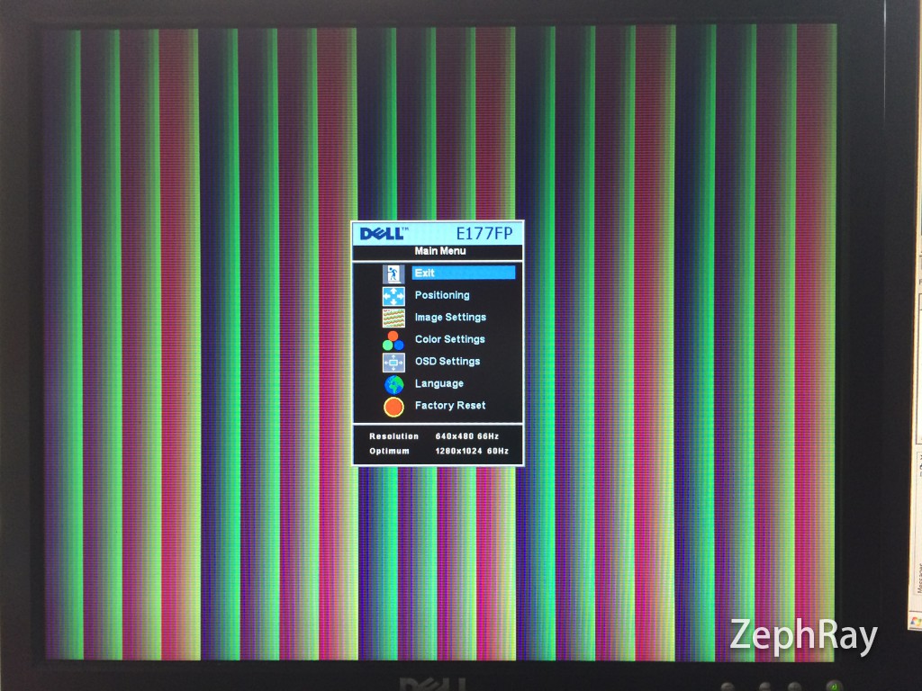
Then simply assign N_Color = N_Address, there would be some image shown on screen:
Next step I decided to let it display some image. To keep things simple I am going to store the image directly in the NOR flash. The only issue is that the NOR flash has 70ns latency, or about 14MHz maxium random access speed. It won't work at 25MHz pixel clock directly. Again to keep things simple I am just going to reduce the resolution to 320x480, so 2 clocks 1 pixel. Generate a 12.5MHz clock and do the following:
always @(posedge V_SLCLK)
begin
  N_Color <= FL_DQ;
  FL_ADDR <= N_Address;
end
Should work now

From 256 colors to 65536 colors
To achieve full resolution + 16bit color, I need something faster, like SRAM and SDRAM. I am going to use SRAM this time. The first thing to implement would be copy data from Flash to SRAM at bootup. So here is the code:
wire DATA_RDY;
reg [18:0] DATA_SEEK = 0;
assign DATA_RDY = (DATA_SEEK == DATA_COUNT) ? 1 : 0;

parameter DATA_COUNT = 460800;

assign FL_CE_N = 0;
assign FL_OE_N = 0;
assign FL_RST_N = 1;
assign FL_WE_N = 1;
assign SRAM_CE_N = 0;

reg [7:0] SRAM_IN;
reg [17:0] SRAM_AIN;
reg [17:0] SRAM_AOUT;
reg SRAM_BIN; //1:UB Activate 0:LB Activate
assign SRAM_ADDR = DATA_RDY ? SRAM_AOUT : SRAM_AIN;
assign SRAM_DQ[7:0] = SRAM_WE_N ? 8'hzz : SRAM_IN;
assign SRAM_DQ[15:8] = SRAM_WE_N ? 8'hzz : SRAM_IN;
assign SRAM_WE_N = DATA_RDY;
assign SRAM_OE_N = !DATA_RDY;
assign SRAM_CE_N = 0;
assign SRAM_LB_N = DATA_RDY ? 0 : (!SRAM_BIN);
assign SRAM_UB_N = DATA_RDY ? 0 : SRAM_BIN;

always @(posedge V_SLCLK or negedge RST_N)
begin
  if(!RST_N)
  begin
    DATA_SEEK <= 0;
    FL_ADDR <= 0;
  end
  else
  if (!DATA_RDY)
  begin
    SRAM_AIN[17:0] <= DATA_SEEK[18:1];
    SRAM_IN <= FL_DQ;
    SRAM_BIN <= DATA_SEEK[0];
    DATA_SEEK <= DATA_SEEK + 1;
    FL_ADDR <= DATA_SEEK;
  end
end
After powering up, the DATA_RDY is 0, so SRAM in write mode, then using the V_SLCLK as the clock, read 1 byte from the Flash and and write into the SRAM. Note the SRAM has 16-bit data bus, so UB and LB signals are needed to write the data to the correct location.
Here is the result:

From VGA to CGA
CGA has the following differences compared to VGA:
- CGA's HSYNC and VSYNC polarity are inversed
- CGA has fixed 15.75kHz line frequency
- CGA uses RGBI 4-bit digital input, up to 16 colors
So don't expect CGA could produce nice looking image... but at least it's simple to modify in the Verilog. First the PLL, I am doing a x31/108, so it gets me the 14.352MHz clock, quite close to the target 14.32MHz.
// Horizontal
parameter H_FRONT = 27; // Front porch
parameter H_SYNC  = 161; // Sync
parameter H_BACK  = 81; // Back porch
parameter H_ACT   = 640;// Active pixels
parameter H_BLANK = H_FRONT+H_SYNC+H_BACK; // Total blanking
parameter H_TOTAL = H_FRONT+H_SYNC+H_BACK+H_ACT; // Total length

// Vertical
parameter V_FRONT = 20; // Front porch
parameter V_SYNC  = 3;  // Sync
parameter V_BACK  = 40; // Back porch
parameter V_ACT   = 200;// Active lines
parameter V_BLANK = V_FRONT+V_SYNC+V_BACK; // Total blanking
parameter V_TOTAL = V_FRONT+V_SYNC+V_BACK+V_ACT; // Total length

assign GPIO_0[1] = !VGA_VS;
assign GPIO_0[3] = !VGA_HS;
assign GPIO_0[5] = N_Enable ? N_Color[3] : 0; //I
assign GPIO_0[0] = N_Enable ? N_Color[0] : 1; //B
assign GPIO_0[2] = N_Enable ? N_Color[1] : 0; //G
assign GPIO_0[4] = N_Enable ? N_Color[2] : 0; //R
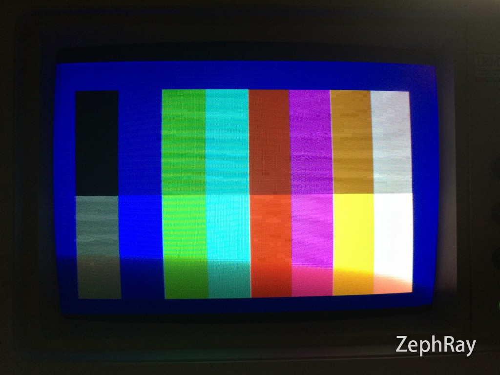
Note that I didn't set the color during blanking to be black, but rather dark blue, and it could be seen in the result. To produce image for CGA, dithering is recommended, though depending on the software one might need to manually input the CGA palette.

And it's... not pretty.
Save the image as bmp, in 4bpp bit depth. Then I am writing a small tool to add some stride, and vertically flip the image for it could be scanned from up to down.
#define BMP_OFFSET 0x76
#define BMP_WIDTH 640
#define BMP_HEIGHT 200

fseek(fpo,0,SEEK_SET);
for (i = 0;i < BMP_HEIGHT; i++)
{
  fseek(fpi,BMP_OFFSET+(BMP_HEIGHT-i-1)*(BMP_WIDTH/2),SEEK_SET);
  fread(linebuf,(BMP_WIDTH/2),1,fpi);
  for (j = 0;j < (BMP_WIDTH/2);j++)
  {
    outputbuf[j*2] = linebuf[j] >> 4;
    outputbuf[j*2+1] = linebuf[j] & 0x0F;
  }
  fwrite(outputbuf, BMP_WIDTH, 1, fpo);
}
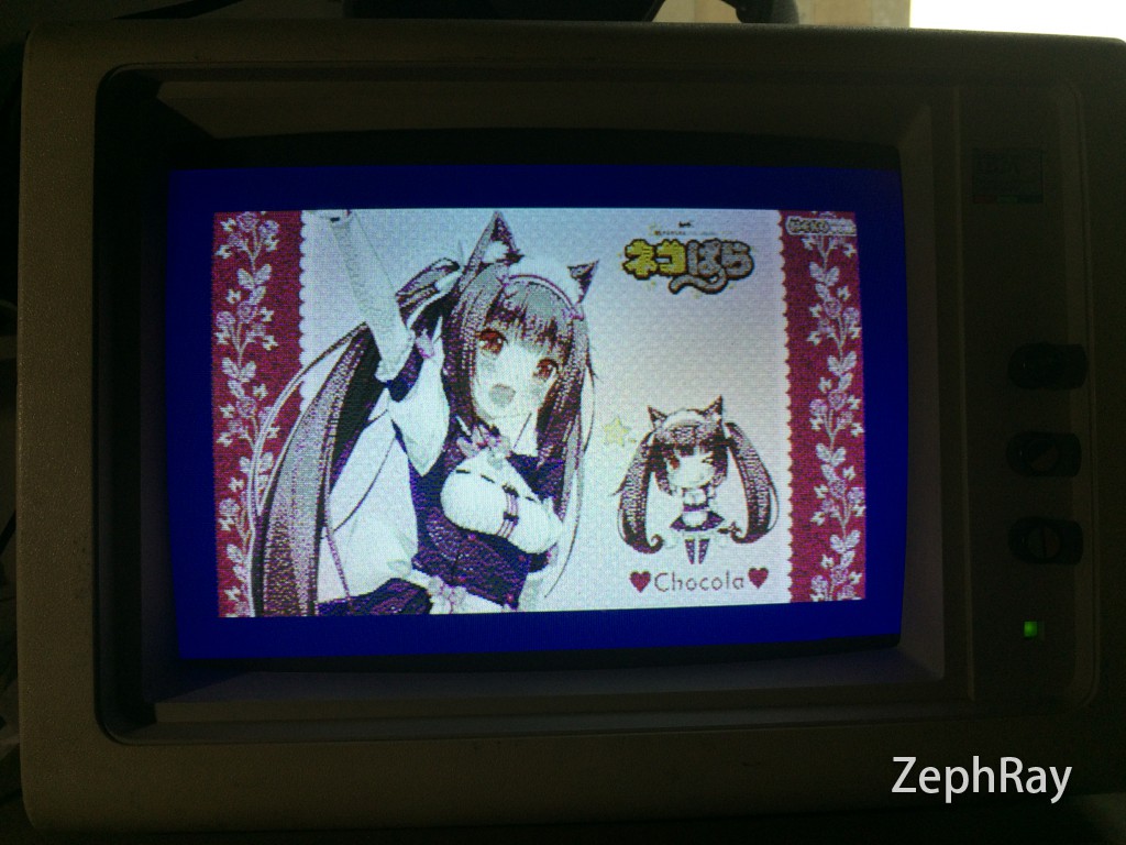
Write the converted file into flash, and here is the result. Remember the dark blue background color I mentioned?
Displaying image:
